
5 ANTENNAS
5.1 INTRODUCTION
In a communication system, one end of the transmission line is connected to the RF output of a radio set, and the far end is modified to allow the RF energy to pass into free space (as we saw in Chapter 4) without being reflected back into the transmission line. This modified section of the transmission line is called the antenna, and the process of transferring the RF energy from inside the transmission line to free space is called radiation. At the receiver, the reverse process occurs, and the receive antenna captures the incident energy in a process called reception and converts it to an electromagnetic wave within a transmission line to travel down to the receiver.
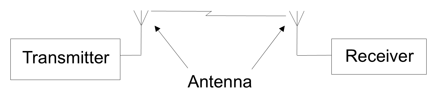
There is little fundamental difference between transmitting and receiving antennas, and very often the same antenna is used for both purposes. This equivalence arises from the reciprocity theorem, which states that under linear, passive, and time-invariant conditions an antenna’s transmitting and receiving characteristics—such as radiation pattern, impedance, and polarization—are identical. Throughout this chapter we describe transmit antennas; reception is invariably the reverse of the transmission process. Figure 5.1 illustrates how an antenna (or aerial) connects the transmitter and receiver to the RF channel through which the electromagnetic wave will propagate.
Antennas play a very important part in a communications system, so it is essential to understand the principles on which they operate. While an antenna can be as simple as a piece of wire, more suitable antenna designs are available. Matching the correct antennas to the transmitter and receiver ensures maximum radiated and received powers. In practice, different applications require unique designs, which has led to the design and development of many types of antenna.
Any conductor carrying a time-varying current produces electric and magnetic fields, but not every wire carrying alternating current is an efficient antenna. Useful radiation occurs when the conductor geometry and current distribution allow part of the field to propagate away rather than cancel or remain stored close to the structure. Radiation efficiency also depends on the antenna's electrical size relative to the wavelength. Figure 5.2 uses a simple straight wire to illustrate the basic mechanism: electrons move back and forth with the alternating current, producing a time-varying electric field.
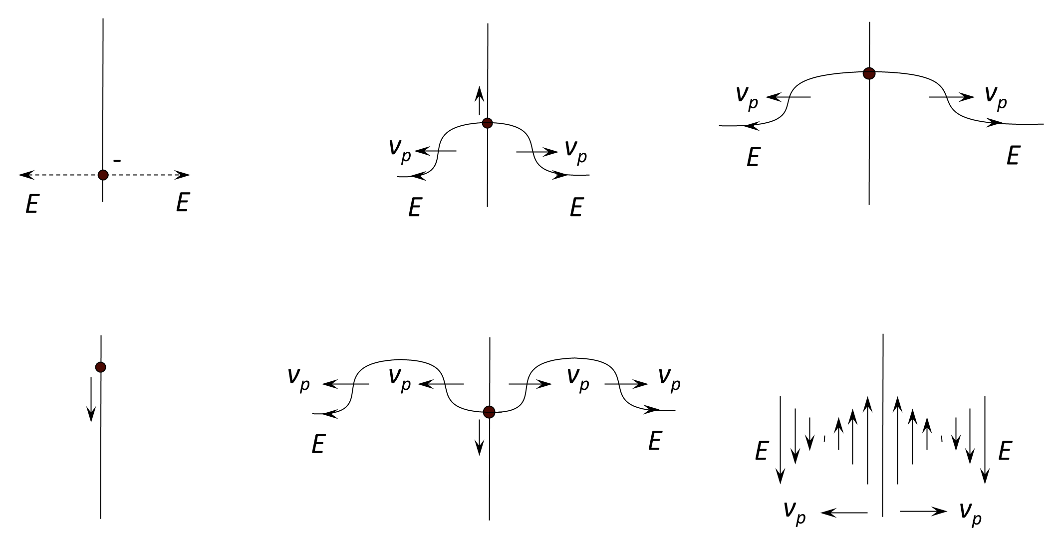
A reasonable physical analogy is that the electron is like a boat moving backwards and forwards in a straight line through the water—the wash of the boat that moves away from the straight line of the boat’s path through the water is similar to the electric field that moves away from the wire.
A time-varying electric field is accompanied by a magnetic field, although Figure 5.2 omits the magnetic field for clarity. The relationship between the two fields depends on distance from the antenna. In the reactive near field, electric and magnetic fields may have different spatial distributions, need not be in phase, and are not constrained to a fixed ratio. As radiation becomes dominant, the fields progressively assume the transverse relationship of a propagating wave; in the far field they are mutually perpendicular and are also perpendicular to the direction of propagation.