5.7 HF SKY WAVE ANTENNAS
Most HF sky-wave antennas are based on a horizontal dipole placed at an appropriate height above the ground to produce the required take-off angle for the radiation (see the patterns of Figure 5.13). Monopoles can be used for sky wave but are best suited for surface wave and direct wave. The following sections address HF sky-wave antennas based on the range required for the communication.
5.7.1 Short Range (0–300 Km)
For short ranges the take-off angle must be between 60˚ and 90˚, which can be achieved by a number of antenna designs including a horizontal half-wave dipole suspended above the ground at a height of λ/8 to λ/4. A three-quarter wave, end-fed antenna is a compromise between a sky-wave and a ground-wave antenna. Under best conditions it radiates approximately 2/3 of the energy as sky wave and 1/3 as ground wave. The quarter wave end-fed antenna can also be used but is not as efficient as a dipole or a three-quarter wave antenna.
5.7.2 Medium Range (300–1,500 Km)
For these ranges, we need radiation angles between 60˚ and 20˚. Depending on the exact angle required, there are several possibilities. Horizontal half-wave dipoles between 0.25λ and 0.6λ above the ground can give angles of radiation between 60˚ and 25˚. The vertical monopole can also be useful for medium ranges producing a radiation pattern with most of the radiation below 40˚, which would give a minimum range of about 250 km using an appropriate frequency for the E layer.
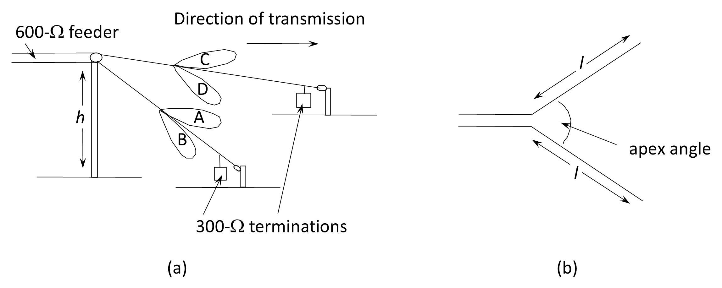
The most useful antenna for medium ranges is the sloping-V antenna, which covers ranges from about 1,200–2,000 km efficiently, and up to 3,200 km less efficiently. The design of the sloping-V antenna is illustrated in Figure 5.22. The antenna is constructed with two wires, several wavelengths in length, arranged in a horizontal V with the apex elevated. The legs of the V are traveling-wave antennas and are terminated in 300-Ω resistors. The antenna is fed at its apex with 600-Ω open-wire line, which is matched to the 72-Ω coaxial cable from the radio by means of a transformer. Lobes A and C add and B and D cancel if the dimensions are correct. The sloping-V is reasonably suitable to field use as it is small and requires only one mast and is reasonably broad-band.