5.3.6 Bandwidth
We will see shortly that the physical dimensions of an antenna are related to the wavelength of operation—the larger the wavelength, the larger the antenna. That generally means that an antenna is built for a particular wavelength and will need to be adjusted in size when the frequency of operation is changed. For many applications, the antenna should preferably not require readjustment when the frequency is changed (within limits of course) and should operate effectively across a range of frequencies—that is, have a wide bandwidth (or be broadband). We discuss antenna bandwidth in more detail in Section 5.4.5, and as we examine the antenna designs that follow, we will identify which are inherently broadband and what modifications may extend operational bandwidth.
5.3.7 Antenna Impedance
A transmission line has a characteristic impedance, and efficient power transfer requires the antenna input impedance to be appropriately matched to the line and transmitter. In an ideal lossless line the characteristic impedance is purely resistive. Practical low-loss RF lines are commonly treated as having a predominantly resistive nominal impedance, such as 50 Ω, although the exact characteristic impedance can contain a small reactive component and vary with frequency.
The input impedance of an antenna depends on its electrical dimensions, current distribution, surroundings, and frequency. It comprises a resistive component and may also contain capacitive or inductive reactance. Reactance is not itself a loss, but it must normally be canceled or transformed so that the transmitter sees its intended load. A correct match minimizes reflected power and maximizes the power delivered to the antenna. The delivered power is then divided between radiated power and losses such as conductor, dielectric, connection, and ground loss; matching alone does not make antenna efficiency 100%.
When the antenna input impedance is equal to the characteristic impedance of the transmission line—and therefore equal to the output impedance of the transmitter—the antenna is said to be matched to the set. Under matched conditions, maximum power is transferred and no power is reflected back along the line.
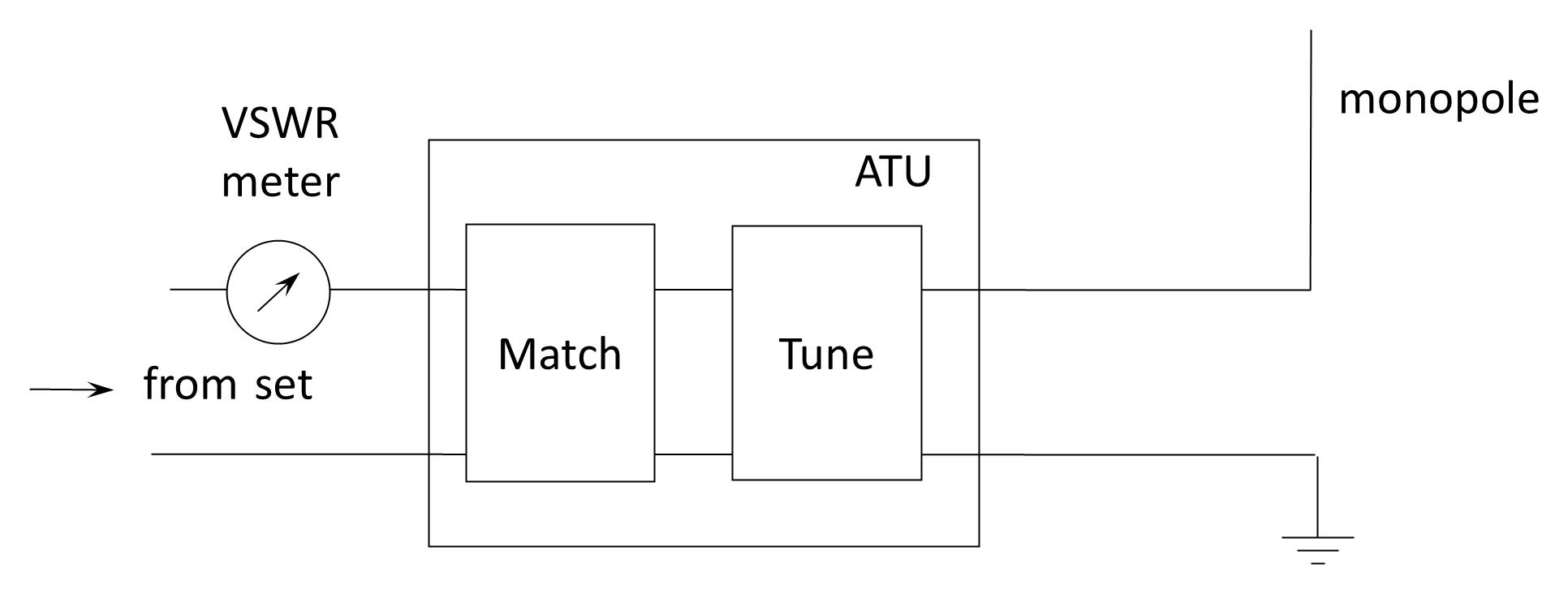
If the radio is to be connected to an antenna whose impedance differs from that of the transmission line, an antenna tuning unit (ATU) is inserted between the set and the antenna to provide impedance transformation. The ATU performs two closely related functions: tuning and matching. In practice these functions are usually achieved simultaneously within a single adjustable network.
- Tuning. If the antenna presents a reactive component (capacitive or inductive), the ATU introduces an equal and opposite reactance so that, at the input terminals of the ATU, the net impedance presented to the transmitter is purely resistive. For example, a short antenna is typically capacitively reactive and requires a series inductance to achieve resonance. Since the electrical length of a fixed physical antenna varies with operating frequency, the reactive component also varies, and the ATU must therefore provide variable inductance and/or capacitance. Adjustment is guided by a reflected-power or VSWR meter, which indicates when the reactive component has been effectively canceled.
- Matching. Once the reactive component has been neutralized (as seen at the transmitter port), the remaining resistive component may still differ from the characteristic impedance of the transmission line (typically 50 Ω in modern systems). The ATU then transforms this resistance to the required value through an impedance-matching network such as an L-, T-, or π-configuration. The objective is to ensure that the impedance presented to the transmitter equals its design load impedance, thereby minimizing reflected power and maximizing power transfer.
An all-purpose ATU therefore consists of a variable reactive network capable of transforming a wide range of complex antenna impedances into the required load impedance for the transmitter. The device is also referred to as an antenna matching unit (AMU) or simply a coupler. It should be noted that the ATU does not change the intrinsic radiation properties of the antenna; it merely ensures efficient transfer of power between the transmitter and whatever impedance the antenna presents.