4 RADIO-WAVE PROPAGATION
4.1 THE ELECTROMAGNETIC WAVE
Before examining the various modes of radio-wave propagation, it is useful to review briefly how a radio wave is created and how it propagates through space. The creation of the wave is discussed in more detail in Chapter 5, when we consider antennas.
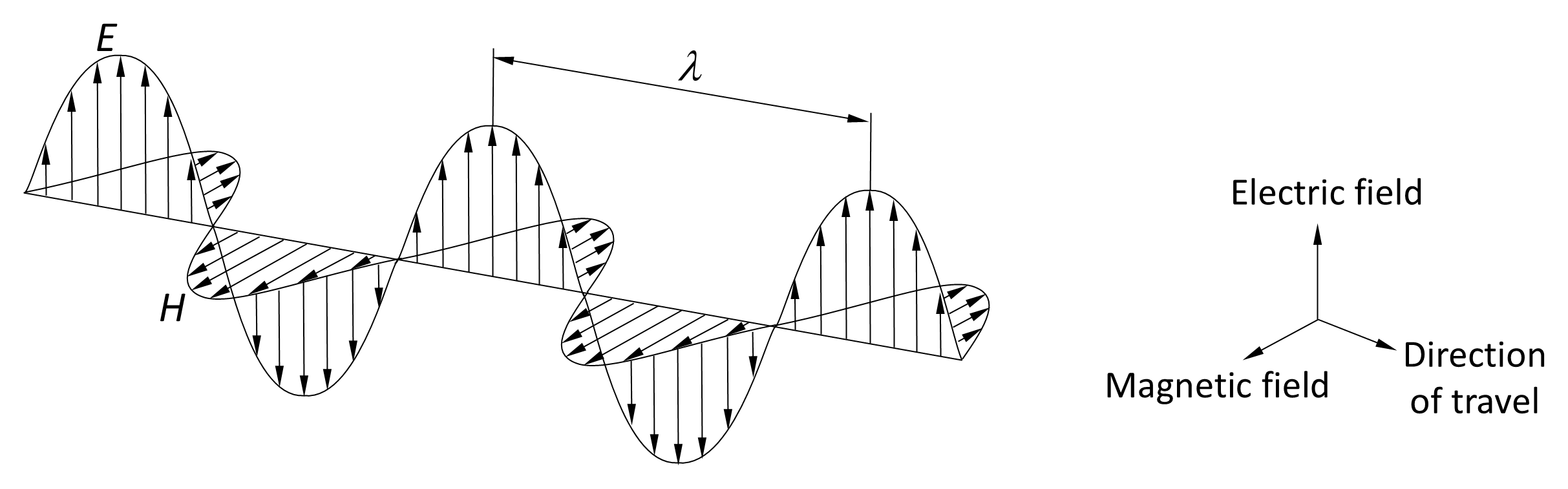
For the moment, consider that a radio wave is typically produced by driving an alternating electric current through an antenna, which is commonly a rod or wire. The alternating current generates time-varying electric (E) and magnetic (H) fields that radiate outward from the antenna. Figure 4.1 illustrates this process for a sinusoidally varying current.
In the far-field region, the resulting radiation is called a transverse electromagnetic (TEM) wave because its electric and magnetic fields are always at right angles to each other and to the direction of propagation. In free space, the magnitudes of the fields are related by the impedance of free space, which has the approximate value of 120 π Ω (≈ 377 Ω):
The wave propagates in free-space at the speed of light c ≈ 3 × 10⁸ m s–1.
The relationships above describe a plane wave in the far field. Close to an antenna, however, the fields pass through the reactive near field and the radiating near field (Fresnel region) before reaching the far field. In the near-field regions, the electric and magnetic fields are not necessarily in phase or related by the free-space impedance, and their spatial variation depends on antenna dimensions, geometry, current distribution, wavelength, and surrounding structures.
This distinction is important in RF radiation safety. In the far field, power density can often be estimated from effective isotropic radiated power (EIRP) and distance, or from either electric-field strength or magnetic-field strength using the plane-wave relationships. In the reactive near field and radiating near field, electric and magnetic fields may need to be assessed separately, and a simple inverse-square calculation may not provide a conservative result. Chapter 5 develops the antenna and field-region concepts; Chapter 8 applies them to exposure assessment.
One of the fundamental properties of a TEM wave is its polarization, which describes the orientation of the electric field as the wave travels through space. If the plane of the electric field is vertical, the wave is said to be vertically polarized; if it lies horizontally, the wave is horizontally polarized. The wave shown in Figure 4.1 is vertically polarized. Vertically polarized waves are radiated by vertical antennas, while horizontally polarized waves are radiated by horizontal antennas.
Vertical and horizontal polarization represent two orthogonal orientations of linear polarization. In circular polarization, the electric-field vector rotates at the same angular frequency as the wave, so that the polarization appears to rotate continuously as the wave propagates. The rotation may be right-handed (clockwise) or left-handed (counterclockwise), as determined by an observer looking in the direction of propagation. In elliptical polarization, the electric-field vector traces an ellipse at a fixed point in space, representing the most general form of polarization; linear and circular polarization are particular cases of this more general condition.