
F.7 MODULE—FIRST ORDER LINEAR NEGATIVE FEEDBACK—EXPLICIT GOAL
F.7.1 General Description
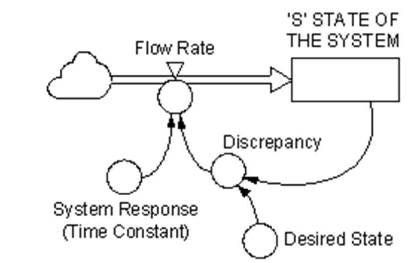
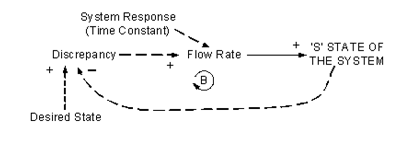
The first-order negative feedback system with explicit goal contains one stock representing the state of the system of interest. Additions are made at a rate proportional to the discrepancy between the actual and desired states of the system. This module is also known as ‘Proportional Control’.
F.7.2 Module Influence Diagram
The influence diagram for this module is shown in Figure F7-2.
F.7.3 Reference Sources
The module is described here after Roberts, et al. (1983: 269-272), Goodman (1989: 54-56), Hannon and Ruth (1994: 30-31) and Sterman (2000: 277-278). Further explanation of this module can be found at Sterman (2000: 277-278).
F.7.4 Application
A simple example might involve a person having specific capacity to react to observed change in state by making adjustments to the input with clear intention of achieving a specific state. Such occurs when we pour liquid from a bottle into a glass, being careful to fill the glass exactly to an imaginary line near the top of the glass.
As we pour from the bottle, we monitor the decreasing gap, that is, the gap between actual and desired levels. Our ability to react is finite. As we pour the liquid it will continue to flow into the glass for a period, even after we have chosen to decrease the flow by raising the bottle up.
The System Response (Time Constant) or Adjustment Time, describes a system characteristic associated which is inextricably linked to the act of the pouring of the liquid and judging the discrepancy: our human capacity to judge and react is limited. We progressively slow down our rate of pouring and try to judge the most appropriate instant to stop pouring, with the aim of exactly achieving the desired state (level of filling). In situations where flow rate is high and system response is slow (represented by a large time constant) it is quite likely that we will overshoot the desired state.
F.7.5 Functional Description
The functions of the various parts of the module are described in Table F7-1.
Table F7-1. Functional Description—First-order Linear Negative Feedback—Explicit Goal—Example
Variable | Function | Comment |
|---|---|---|
‘S’ STATE OF THE SYSTEM | This is the actual state of the system under examination. Units of ‘S’ STATE OF THE SYSTEM and Desired State are the same, say <<litres>>. | |
Flow Rate | ‘S’ STATE OF THE SYSTEM *Discrepancy* System Response (Time Constant) | Units will be, say <<litres/minute>>, calculated as: <<litres>>*<< dimensionless >>*<<(a constant, that is, dimensionless)>>*1/<<time>> |
Discrepancy | ‘S’ STATE OF THE SYSTEM / Desired State | Because ‘S’ STATE OF THE SYSTEM is a proportion of Desired State, we have proportional control. |
Desired State | This is the desired state of the system under examination. | |
System Response (Time Constant) | This is a characteristic of the system being analysed. It indicates the ability of the system to react to changing conditions, that is, changes in the discrepancy to which the system response is an altered Flow Rate. This is a time constant and is dimensionless. |
References
- Roberts, N.R., Andersen, D.F., Deal, R.M., Garet, M.S. and Shafer, W.A., 1983, Introduction to Computer Simulation: The System Dynamics Approach, Productivity Press, Portland Oregon.
- Goodman, M.R., 1989, Study Notes in System Dynamics, Productivity Press, Portland, Oregon.
- Hannon, B. and Ruth, M., 1994, Dynamic Modelling, Springer-Verlag, New York.
- Sterman, J.D., 2000, Business Dynamics: Systems Thinking and Modelling for a Complex World, Irwin McGraw-Hill.