
F.15 MODULE—PIPELINE DELAY ARRAY
F.15.1 General Description
The action of a pipeline delay can be likened to that a conveyor belt: items travelling on a conveyor belt travel for a known time and the order in which items are placed on the conveyor belt is the order in which they come off. The description pipeline delay suggests, in a pipeline metaphor, that what is pumped into the pipeline first, exits the pipeline first. The pipeline delay is a device operating according to a first-in, first-out (FIFO) protocol. Noting that the speed of flow through the pipeline, or along the conveyor belt, is pre-determined by the inflow rate, the length of the pipeline or conveyor belt determines the length of the delay. Note that the inflow and outflow rates are inextricably linked: the contents of the pipeline are not compressed or do not expand as they flow through the pipeline. Also, items in the pipeline or on the conveyor belt are unavailable elsewhere in the model for the time they are delayed. A pipeline delay is fundamentally a mechanism where contents flow through in a pre-determined way and take a pre-determined length of time: it is an ageing mechanism.
Powersim™ Studio has a built-in Pipeline Delay function ‘DELAYPPL’. However, building a module which is an array version of the ‘DELAYPPL’ function is a valuable exercise. Once completed, the modeller can set the extent of the delay by changing the dimensions of the array elements. This provides precision and control. Such a module is readily tested to ensure that the delay operates exactly as it should. This module can be further developed to have several dimensions according to various attributes of an aging or delay process to be modelled.
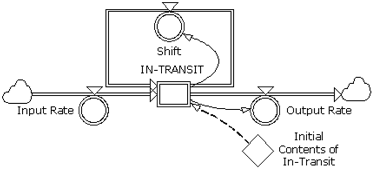
F15-1. Pipeline Delay Array Module
F.15.2 Causal Diagram Representations
Using influence diagram conventions, delay mechanisms are shown without necessarily specifying the type of delay involved. The influence diagram for a generic delay is shown at Figure 15-2.
In causal-loop diagramming convention, shown in Figure F15-3, depiction again appears without necessarily specifying the type of delay involved:
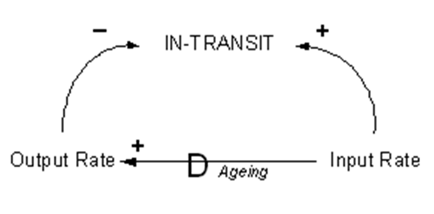
F15-2. Influence Diagram for Delay Module
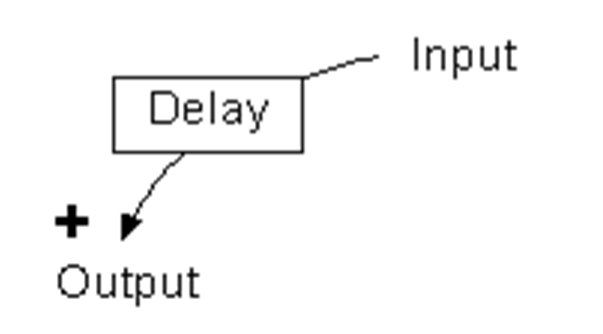
F15-3. Partial Causal Loop Diagram Showing a Delay
F.15.3 Application
Pipeline delay array model demonstrated here can be used to model:
- aging processes, and
- FIFO services to customers where the service provided to each customer takes exactly the same amount of time.
An example of the application of this module might be where personnel in a human resources management succession situation have to spend a fixed time in rank (TiR) before being eligible for promotion, or have to spend a fixed time undergoing training before being employed on those tasks for which they are being trained.
F.15.4 Functional Description
The stock, level or accumulator IN-TRANSIT holds generic items called items. Units of simulation are items and flows occur at the rate of items /unit of time, where unit of time is arbitrarily set as days. Items arrive to be placed in the stock IN-TRANSIT at a rate, Input Rate. For demonstration purposes, the Input Rate has been created to present random numbers for input.
Imagine the stock IN TRANSIT as having a number of compartments arranged vertically like rungs of a ladder. Each timestep, a randomly generated number of items arrive and are placed in the lowest compartment or on the lowest rung. Each subsequent timestep the items in each compartment are moved simultaneously to the next higher compartment. This process repeats until the items arrive at the top compartment from which they are removed via the Output Rate.
The pipeline can be empty at the start of the simulation. For most simulations this is undesirable since this causes the model to run for some time before any output is achieved. To avoid this transient situation, the pipeline is filled before the simulation starts. This is achieved by placing chosen numbers of items in each compartment using the Initial Contents of In-Transit auxiliary.
The Shift auxiliary is the device which simultaneously selects the items from each of the compartments in IN-TRANSIT and places in them in the corresponding next highest compartments. Because Shift performs the function of selecting the contents of each of the lower compartments simultaneously, it has array dimensions one less than IN-TRANSIT. Shift does not perform any operation on the contents of the highest compartment. The contents of this compartment cannot be raised to any compartment or rung on our ladder any higher than the (n-1)th increment levels (compartment or rung). The number n denotes the number of increment levels in IN-TRANSIT: they are removed and exit via the Output Rate.
For demonstration purposes, after three steps of a simulation the module appears as shown below. Note how the initial values of the array Initial Contents of In-Transit have moved to positions 4 and 5 of the IN_TRANSIT array whilst the lower positions have been filled by randomly generated numbers of items input via Input Rate and each subsequently incremented to the next higher compartment in IN-TRANSIT via the action of the Shift auxiliary.
The functions of the various parts of the module shown in Figure F15-4 are in Table F15-1.
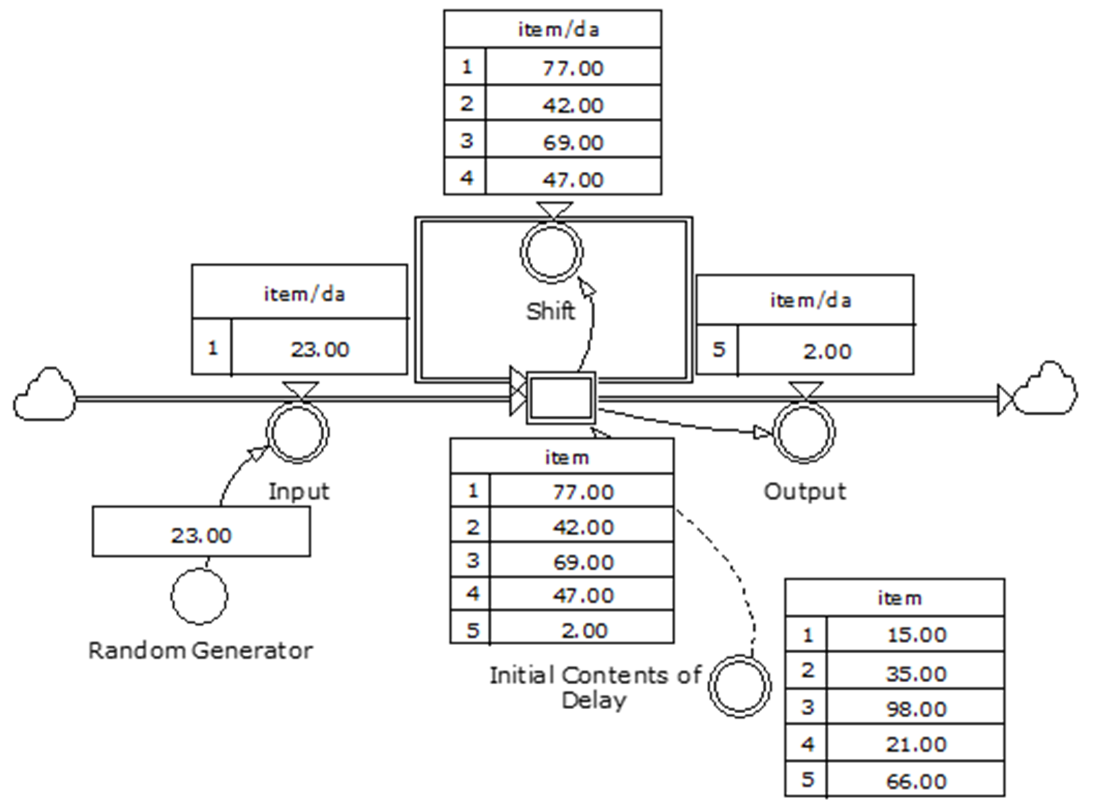
F15-4. Stock-and-flow Diagram Showing Summary Simulation Results for Pipeline Delay Array
Table F15-1. Table Defining Variable Functions for Pipeline Delay Array
Variable Name | Function | Comment |
|---|---|---|
Random Generator | ROUND(100 *(RANDOM(0,1,.45))) | Generates numbers between 0 and 100. For demonstration purposes, this is a convenient device for providing a sequence of appropriate numbers to input into the model via the Input Rate variable. The progress of this sequence through the module is easily followed. |
Input Rate | 'Random Generator'* 1<<item>>/1<<da>> | The auxiliary variable named Input Rate controls the flow valve connecting the pipe from the problem space boundary, represented by the cloud, to the state variable (stock, level or accumulator) named IN-TRANSIT. In this case, Input Rate has array dimensions ‘1..1’ which means that whilst it is an array variable we are only exploiting the first incremental level, or dimension, of the array. Scalar numerical values are input as a sequence of numbers, where one number is generated corresponding to each simulation timestep. Please note that we can count numbers of timesteps performed as we simulate the module. In contrast to timestep, dt is the elemental slice in time taken by Powersim™ for the purposes of performing its calculations, each of which involves making numerical approximations. The selection of dT, timestep, time horizon and method of integration are all important factors in correctly setting up a simulation. Note: In all modelling activities, it is essential to ensure that units used are both correct and consistent. Powersim™ Studio is designed to enforce this. Earlier versions and some other system dynamics applications do not enforce this discipline. To ensure consistency in the units used in the model, noting that Random Generator produces one number each timestep and those numbers have no units assigned to them, it is necessary to assign units to the numbers being processed by the auxiliary Input Rate. This is achieved by multiplying each of the numbers in the sequence generated by the units needed: *1<<item>>/1<<da>>, where the double chevrons << , and >>, on either side of the units indicate that the units have been manually inserted. Resulting units are items / day. Where units do not need to be manually inserted, that is, where units have been automatically assigned, the variable will appear inside inverted commas, such as ‘IN-TRANSIT’. In cases where we have to create consistent units such as where a fictitious rate variable, throughput might have the units of items already assigned to it, we will need to divide this by a factor to create correct units, noting that all rate variables involve numbers (with or without units assigned) divided by time. To make the correction to our fictitious rate variable ‘Throughput’, we operate on it by: /1<<da>>, where the model timestep is defined in days. |
Initial Contents of In-Transit | {15,35,98,21,66} | This auxiliary variable has been assigned the array dimensions ‘1..5’, and the initial values of this variable are: {15,35,98,21,66}. Units of this variable are items. |
IN-TRANSIT | 'Initial Contents of In-Transit' | IN-TRANSIT is a state variable, alternatively called a stock, level or accumulator. The convention used throughout this book is to identify state variables using upper case. IN-TRANSIT has the array dimensions ‘1..5’, the same as Initial Contents of In-Transit, and units of items. When the simulation starts, the initial values of Initial Contents of In-Transit are transferred into IN-TRANSIT as the starting values. Each timestep after that, one new value is inserted at the lowest incremental level in this state variable. An appropriate metaphor might be of a step ladder: at the beginning of the simulation, at the first timestep, the relevant numbers of items are placed on each of the five rungs from the bottom up are 15,35,98,21 and 66 respectively; at the second timestep, a new number is transferred from the rate variable Input Rate and appears on the lowest rung. At the same time each of the numbers originally appearing on the rungs is moved up one by action of the aging loop containing the auxiliary named Shift. The number that was originally on the top step moves through the rate variable named Output Rate. The Flow Definition (found by double clicking on the IN-TRANSIT symbol then opening the Flows dialog box in the ‘IN-TRANSIT’ Level Symbol Properties) is automatically generated by Powersim™ Studio. However, it is essential to connect the flows to the IN-TRANSIT icon in the following sequence: Input from Input Rate Output to Shift Input from Shift Output to Output Rate If this is not the sequence that appears under ‘Flows’ tab, correction is achieved by temporally disconnecting the flow pipes from the IN-TRANSIT stock and reconnecting them by dragging then to the IN-TRANSIT icon in the sequence indicated by the dot points above. |
Shift | 'IN-TRANSIT'[1..4] /1<<da>> | This rate variable has one fewer dimensions than the state variable IN-TRANSIT. Each timestep, each of the four numbers on the lower rungs of our metaphorical ladder are advanced one higher. The top one is displaced by the action of the rate variable Output Rate and disappears outside the model boundary. |
Output | 'IN-TRANSIT'[5..5] *1/1<<da>> | The number at the top rung of our metaphorical ladder named IN-TRANSIT is taken and pumped through the valve controlled by the rate variable called Output Rate. Note that Output Rate has array dimensions ‘5..5’, meaning that it only operates on the numbers on the top step of our five rung stepladder. According to the way this model is constructed, it is only the number on the top step of the ladder that is ever picked up and moved through this rate variable. |