6.4.8 Flow Calculation Sequence
Powersim™ Studio performs calculations of flows into and out of each stock (level or accumulator) in very specific sequences. Why a specific sequence of calculations is necessary is best explained by use of an analogy: we first have to add water to a bathtub before we drain water from it.
The sequence of calculation is important even though connections to a particular stock in a model you have constructed may result in flows out being calculated before flows in, may not cause obvious problems. It is necessary to deliberately check the sequence of calculations even when the model appears to behave properly. This is because in subsequent developments of the model the addition of inflows or outflows may actually result in an incorrect sequence of calculations.
Though it might seem trivial, construct the following simple model at Figure 6-2.
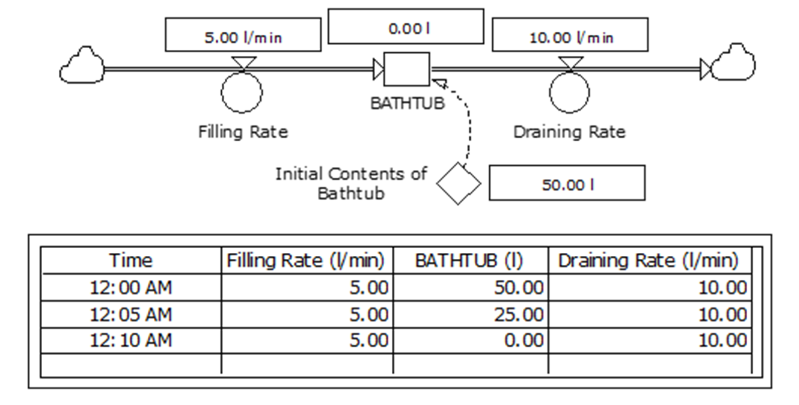
The flow calculations made automatically by Powersim™ Studio are:
+ dt * (Filling Rate)
– dt * (Draining Rate)
This means that for each timestep:
- the amount added will be Filling Rate multiplied by the increment of time used by Powersim™ Studio in its calculations;
- the amount subtracted will be Draining Rate multiplied by the increment of time used by Powersim™ in its calculations; and
- the amount added will be calculated before the amount subtracted.
In this instance, the sequence of calculations may be reversed with no real effect. This can be demonstrated by temporarily disconnecting each of the flow pipes from the stock BATHTUB before reconnecting them in the desired order. Each time this is done, the sequence of calculations can be checked by opening ‘BATHTUB’ Level Symbol Properties dialogue box and looking at Flows properties.
Consider an example, Figure 6-3, where the sequence of calculations does matter. Here, the stock IN-TRANSIT not only contains each of the values of the state variable, but each is held in one of several dimensions. Array elements are added via the Input Rate, along the flow pipe indicated by the arrow marked ‘1’. A temporary (conceptual) outflow, along the flow pipe indicated by the arrow marked ‘2’, indexes the array elements to the next higher dimension. After being indexed to the next higher dimension, array elements are re-positioned in the IN-TRANSIT array, flowing via the pipe as indicated by the arrow marked ‘3’. The indexing via the Shift auxiliary, following arrows marked ‘2’ and ‘3’ until elements are positioned in the highest array dimension. It is only those elements that can be promoted out via the pipe indicated by the arrow marked ‘4’ through the Output Rate.
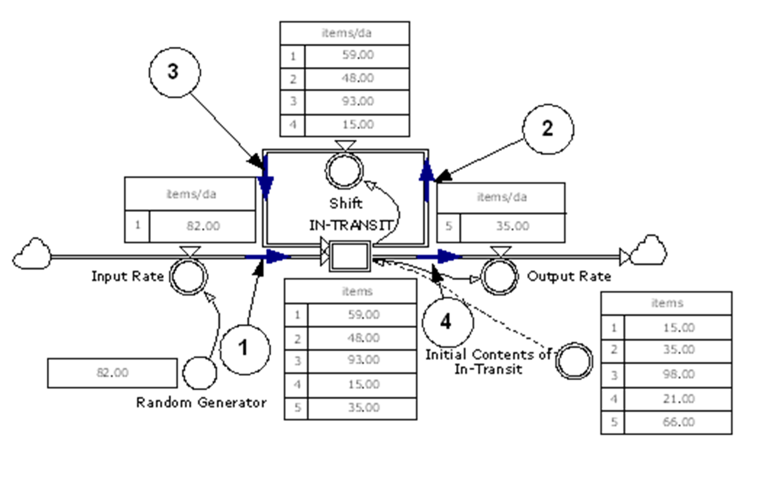
Table 6-1. Definitions for Variables in Generic Ageing Array Module
Variable | Definition | Comment |
|---|---|---|
Random Generator | ROUND(100*(RANDOM(0,1,.45))) | Generates integers in the range 0-100, randomly distributed. |
Input Rate | 'Random Generator'*1<<item>>/1<<da>> | Dimension: 1..1 |
IN-TRANSIT | 'Initial Contents of In-Transit' | Dimension: 1..5 |
Shift | 'IN-TRANSIT'[1..4]/1<<da>> | Dimension: 1..4 |
Output Rate | 'IN-TRANSIT'[5..5]*1/1<<da>> | Dimension: 5..5 |
The key variables of the model at Figure 6-3 are defined at Table 6-1. Also see Appendix F.15
Each timestep, each of the elements of the array IN-TRANSIT are raised to the next higher increment by the Shift auxiliary. But before that can happen, a new element to be inserted at the first position in the array IN-TRANSIT must be received. As a result of each element being shifted up one position in the array IN-TRANSIT, one element is left without a position in the array. This element is then processed through the Output Rate auxiliary. The order is essential.
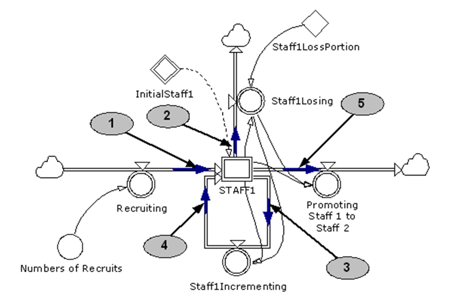
The order is also essential where there are several flows out of a stock and these can only happen in a specific order. In a human resource management model such as that shown in Figure 6-4:
- individuals may choose to leave employment; whilst
- only individuals remaining, that is, those who have not chosen to leave can be considered for advancement to the next incremental level, and then considered for promotion.
Again the sequence of flows must be correctly set according to that indicated by the numbered arrows. See Figure 6-4, Appendix F.16, and Figure 5-14.
Note that several information flow lines have been added. These reflect the governing business rules which have been incorporated into the module. These governing business rules must be fully documented, progressively added and tested to ensure that they do not contravene logic and mass-balance tests, and are robust when subjected to extreme-value tests.
Establishing the correct sequence of calculations is achieved by temporarily disconnecting each of the flow pipes from the stock and reconnecting them in the order indicated. Once this has been done, the sequence of calculations can be checked by opening ‘STAFF1’ Level Symbol Properties dialogue box and looking at Flows properties.