
F.3 MODULE—TRANSITIONAL (IRREVERSIBLE) FLOW
F.3.1 General Description
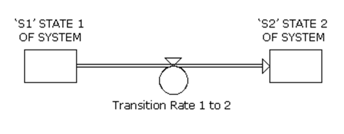
As depicted at Figure F3-1, transitional (irreversible) flow occurs from an initial state to a final or subsequent state. The rate-controlling variable Transition Rate 1 to 2 controls the rate at which the conversion from ‘S1’ STATE 1 OF SYSTEM to ‘S2’ STATE 2 OF SYSTEM or physical flow between the stocks. This module is also known as ‘Conversion’ because it represents the conversion, being a change of state of members or items contained in an initial stock or having an initial state.
F.3.2 Module Influence Diagram
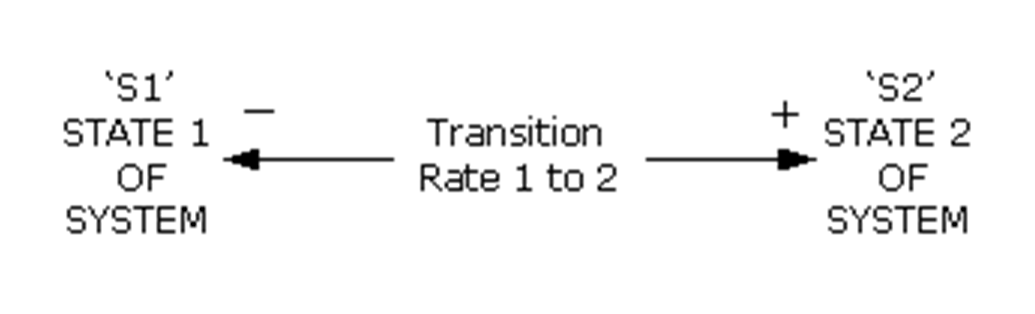
The influence diagram for this module is shown in Figure F3-2.
F.3.3 Reference Source
The module is described here after Coyle (1996: 38).
F.3.4 Example Applications
In continuous models, we would envisage flow of a fixed amount of water from the first bathtub to the second bathtub. The first bathtub empties as the second one fills. Once the contents of the first bathtub have been exhausted, flow stops. This forms the basis for creating models, such as the Bass diffusion model (Sterman, 332-339), designed to analyse mechanisms underlying the conversion of initial users or adopters from one product to an alternative product. In instances where flow is reversible, the module described in Appendix F4 applies.
In a discrete event model, that is, where rates take on discrete values (either 0 or 1, for example), this module could be used to depict a logic device where ‘S1’ STATE 1 OF SYSTEM would take on the value 0 or 1 when ‘S2’ STATE 2 OF SYSTEM takes on the corresponding values of 1 or 0.
This module might be used to monitor the flow of a fixed amount of material or a fixed number of items from one stock ‘S1’ STATE 1 OF SYSTEM to the second stock ‘S2’ STATE 2 OF SYSTEM. Once this has occurred or a specific level achieved in ‘S2’ STATE 2 OF SYSTEM:
- the simulation would be halted;
- in another part of the model, connected by an information line:
- flow would be ceased; or
- flow would be diverted (that is, implementation of an alternate policy once a particular state has been achieved).
F.3.5 Functional Description
The functions of the various parts of the module are described in Table F3-1.
Table F3-1. Functional Description—Transitional (Irreversible) Flow
Variable | Function | Comment |
|---|---|---|
‘S1’ STATE 1 OF THE SYSTEM | x | Initial Stock S1 – dt * (Transition Rate 1 to 2) Initial value of S1 = x Units: <<items>> or <<material>> Note that in Powersim™ Studio the characters (‘) and (’) are illegal for naming and would have to be avoided when creating the names for variables. An alternative might be S1-STATE1 OF THE SYSTEM. |
Transition Rate 1 to 2 | Defined as required. Units: <<items/time>> Note that to safeguard against attempting to remove more material from STOCK 1, that is, ‘S1’ STATE 1 OF SYSTEM’, than it contained at the start of the simulation (x <<items>>), a logical (Boolean) constraint in the following form would be required, as a multiplier to the expression defined for Transition Rate 1 to 2: * IF (‘S1’ STATE 1 OF THE SYSTEM < 0 <<items>>, 0, 1) This will require the addition of an information link from ‘S1’ STATE 1 OF THE SYSTEM to Transition Rate 1 to 2. | |
‘S2’ STATE 2 OF THE SYSTEM | y | Initial Stock S2 + dt * (Transition Rate 1 to 2) Initial value of S2 = y Units: <<items>> or <<material>> |
References
- Coyle, R.G., 1996, System Dynamics Modelling: A Practical Approach, Chapman and Hall, London.