3.1.8 Flowing Out Powersim™ Studio Module
The project and simulation settings needed for the creation of this module and running of the simulation are identical to those for the Flowing In module and are not re-stated. The basic requirements for a module which we will design to analyse Flowing Out can be derived from Figures 3-16, 3-17, and 3-18. These are shown at Figures 3-29, 3-30, and 3-31.
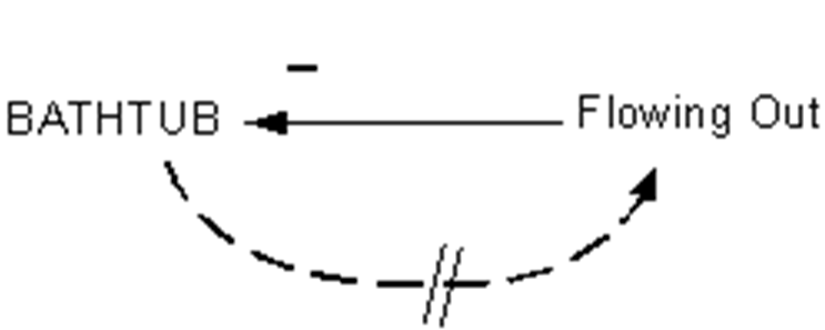
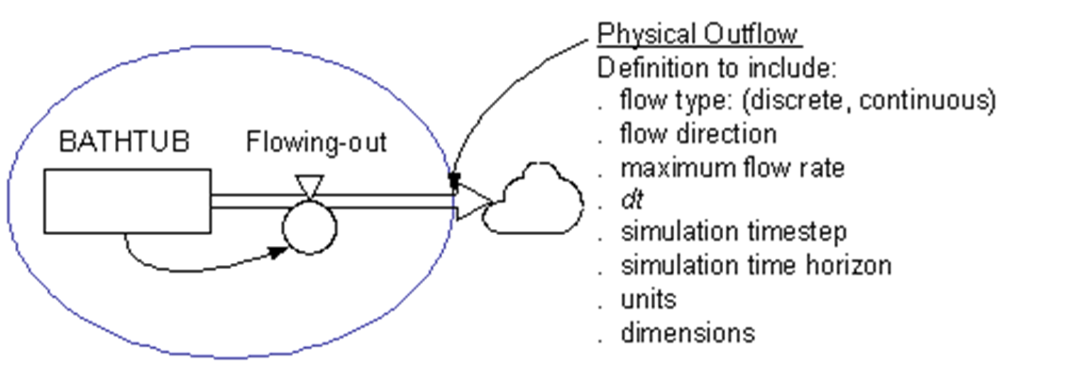
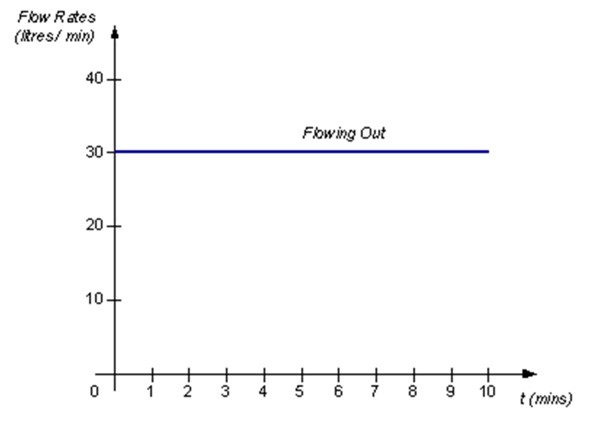
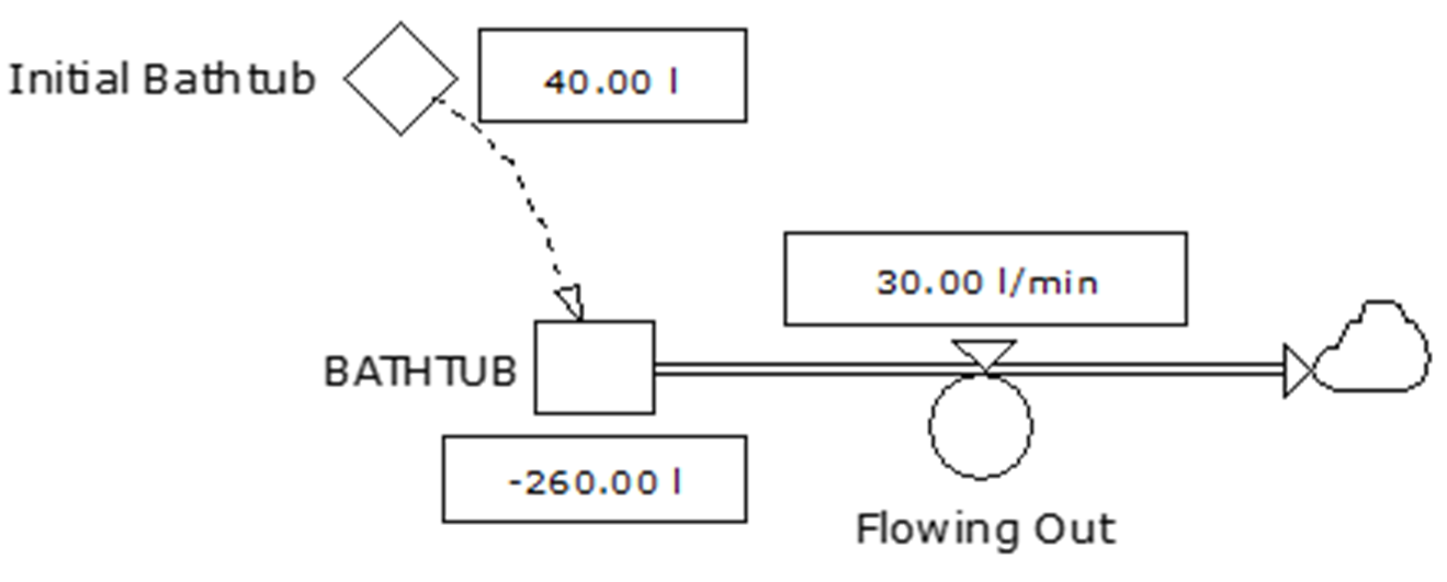
The module is defined at Table 3-4.
Table 3-4. Definition of Flowing Out Module
Variable | Variable Type | Units | Definition |
|---|---|---|---|
Flowing Out | Rate variable. Continuous physical flow. Material flowing is water. | litres / minute | Flow from module across boundary to the outside. Maximum flow rate = 30 litres / minute. Figure 30 shows rate of Flowing In. Simulation starts at t = 0 and runs until t = 10. |
BATHTUB | State variable. | litres | Stock of water. Initial value is 40 litres. Maximum = 300 litres. Minimum = 0 litres. |
Project and Simulation Settings. The project and simulation settings needed for the creation of this module and running of the simulation are the same as those defined for the Flowing In module. The Flowing In module developed in Powersim™ Studio is described below. The constructor diagram with auto reports displayed at the end of the 10-minute simulation is shown at Figure 3-32.
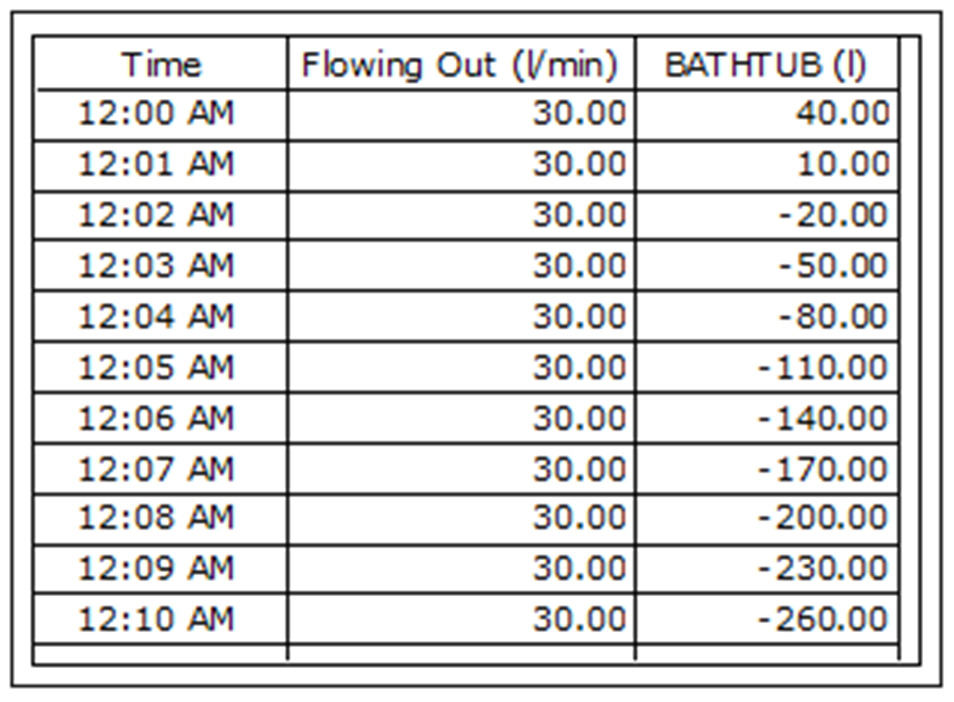
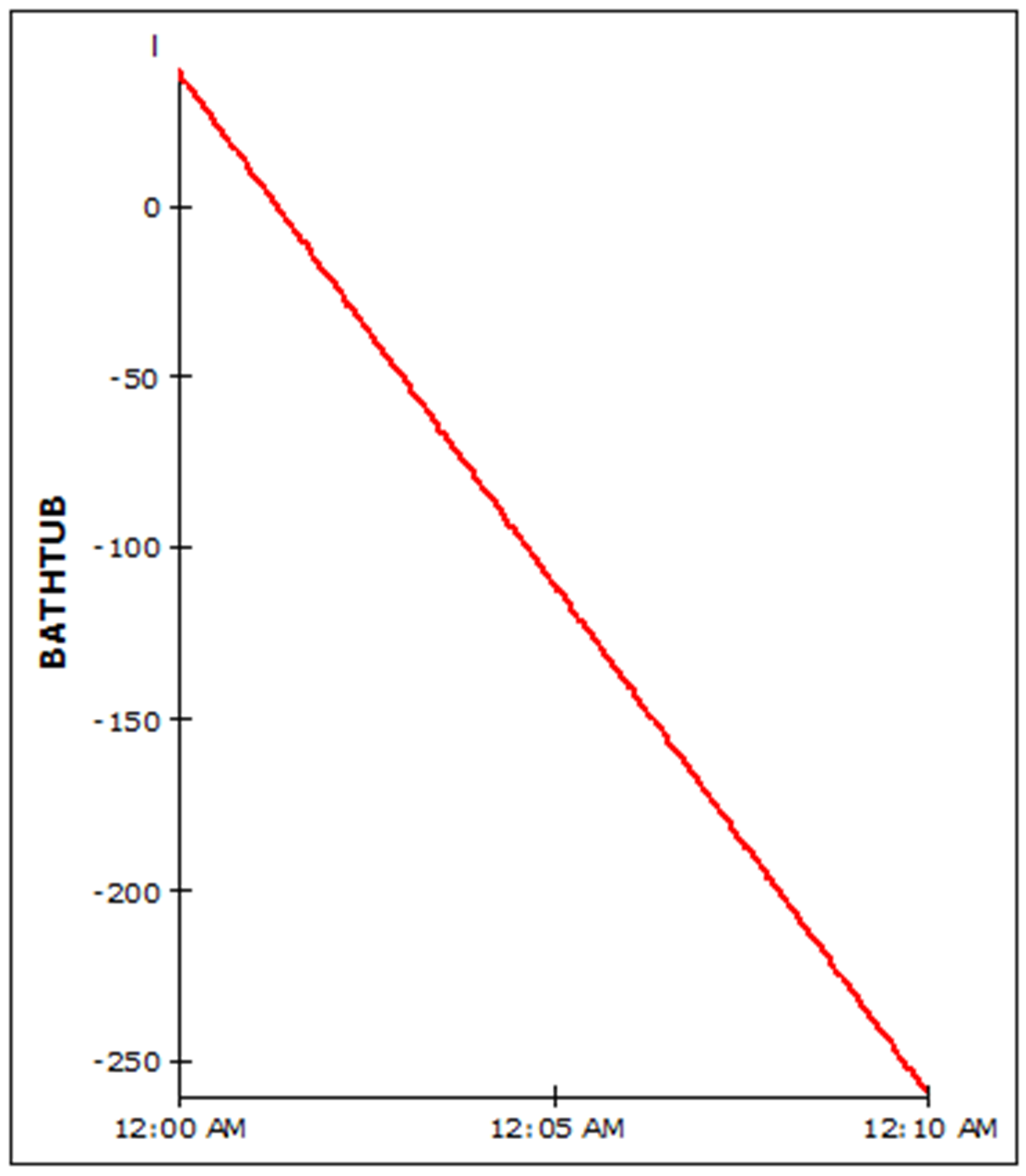
The results of defining Flowing In as described at Figure 3-31 and Table 3-4 (but, initially ignoring the minimum value of BATHTUB) are shown at Figure 3-33 and 3-34.