12.9.4 Microstrip Patch Antennas
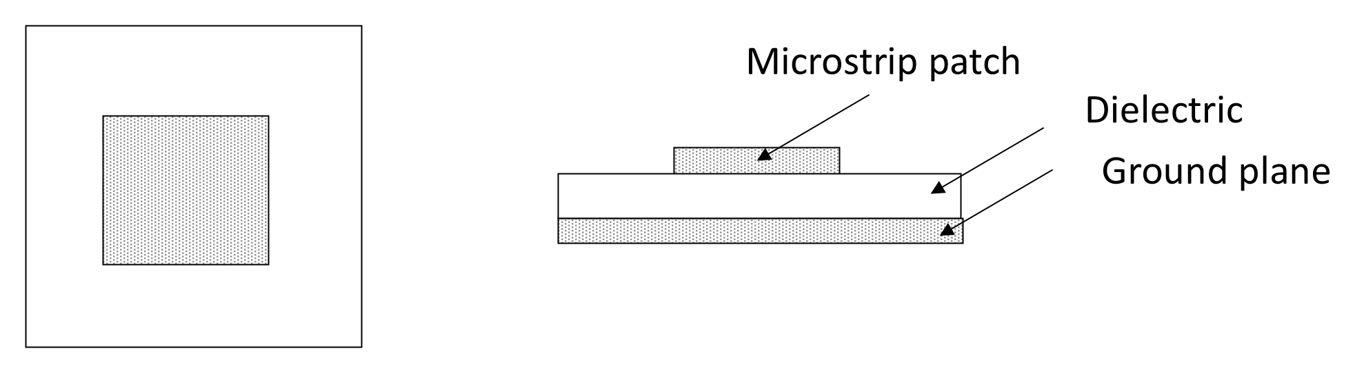
A microstrip antenna consists of a thin metallic radiating patch printed on one side of a dielectric substrate, with a continuous ground plane on the opposite side. Although almost any planar shape may be used (rectangular, circular, triangular, elliptical, etc.), at least one physical dimension of the patch is typically approximately one half-wavelength in the dielectric medium. Figure 12-44 illustrates a simple rectangular microstrip patch antenna. Because the wavelength in the substrate is reduced by the square root of the relative permittivity, the physical length of the patch is approximately:
where λ0 is the free-space wavelength and εr is the substrate relative permittivity.
Microstrip patches radiate primarily due to fringing fields at the radiating edges of the patch. The ground plane suppresses backward radiation, producing a predominantly unidirectional pattern normal to the surface of the substrate. A single rectangular patch typically provides a gain of approximately 4–7 dBi, with a broad beamwidth and moderate front-to-back ratio.
A principal limitation of the basic microstrip patch is its inherently narrow bandwidth. Because it behaves as a resonant cavity radiator with relatively high Q, the typical impedance bandwidth for a simple, single-layer rectangular patch is on the order of 2–5% (for VSWR ≤ 2:1). The bandwidth decreases further when high-permittivity substrates are used to reduce physical size. Radiation efficiency may also be limited by issues such as dielectric losses in the substrate, surface-wave excitation (particularly for thick or high-εr substrates), and conductor losses in thin metallization.
These effects can reduce efficiency compared with larger wire or aperture antennas, particularly at higher microwave frequencies.
Nevertheless, numerous techniques exist to extend bandwidth and improve performance, including: use of thicker, low-permittivity substrates, stacked patches (multi-resonant structures), aperture-coupled or proximity-coupled feeds, parasitic elements, and slotting or shaping of the patch. With such methods, fractional bandwidths of 10–20% or more can be achieved in practical designs.
Microstrip patches readily support both linear and circular polarization. Linear polarization is achieved with a single feed placed at an appropriate location along the patch. Circular polarization may be obtained by dual orthogonal feeds with a 90° phase shift, or by perturbing the patch geometry (for example, truncated corners in a square patch) to excite two orthogonal modes in quadrature. This flexibility makes patch antennas particularly attractive for satellite communication systems, where circular polarization is often preferred to mitigate polarization mismatch due to spacecraft rotation or Faraday rotation in the ionosphere.
Microstrip patch antennas possess several attributes that are highly attractive in satellite communications and aerospace applications: low profile and conformal geometry, allowing installation on curved surfaces; lightweight construction, important for airborne and spaceborne platforms; ow manufacturing cost, compatible with printed-circuit and photolithographic processes; and ease of integration with microwave monolithic integrated circuits (MMICs) and optoelectronic integrated circuit (OEIC) technologies.
Despite their individual limitations in bandwidth and efficiency, microstrip patches are the dominant radiating elements in modern phased arrays. Their planar structure enables dense two-dimensional array layouts on a common substrate, facilitating large element counts with high repeatability. The feed network, phase shifters, bias networks, and transmit/receive modules can be integrated directly behind or beneath each patch, minimizing feed losses and enabling compact active electronically scanned arrays (AESAs).
Because patches can be arranged with small inter-element spacing (typically ≤ 0.5λ), wide scan angles may be achieved while controlling grating lobes. This makes microstrip technology particularly well suited to electronically steerable satellite terminals, radar systems, and emerging flat-panel user terminals for non-geostationary satellite constellations.
In summary, the microstrip patch antenna is a compact, planar, resonant radiator offering moderate gain, polarization flexibility, and exceptional compatibility with modern microwave fabrication techniques. Although constrained by narrow intrinsic bandwidth and moderate efficiency, its scalability and integrability have made it the foundational element of contemporary microwave and satellite antenna arrays.