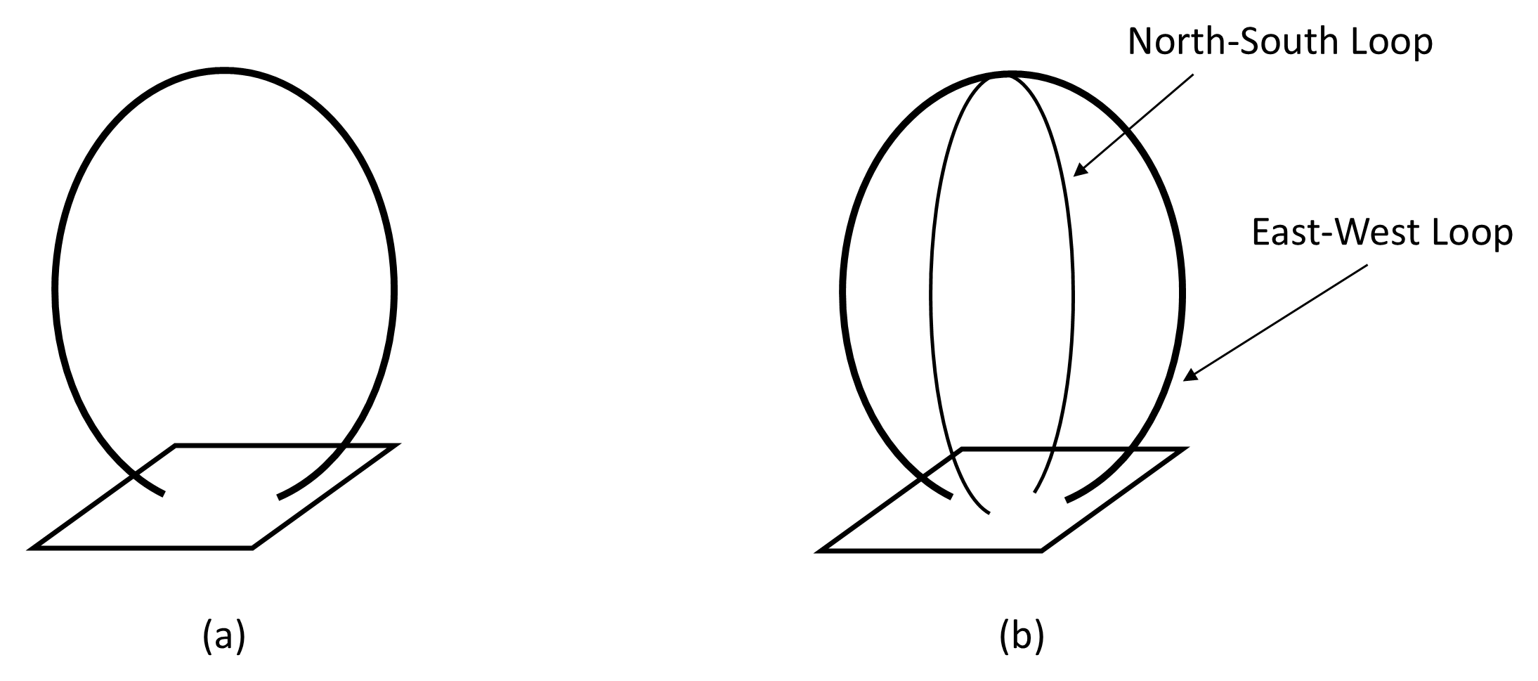
12.8.6 Loop Antenna
A loop antenna consists of one or more turns of conductor arranged in a closed path, usually circular, square, or rectangular. Unlike the dipole, which responds primarily to the electric field component of an incoming wave, a small loop antenna responds mainly to the magnetic field component. For this reason, it is sometimes referred to as a magnetic loop antenna. Loop antennas are widely used at LF, MF, and HF, particularly where compact size, directional properties, or noise rejection are important.
Loop antennas are commonly classified depending on their electrical circumference relative to the wavelength as small loops with a circumference much less than one wavelength (typically < λ/10) or large loops with a circumference comparable to or greater than one wavelength.
In a small loop, the current is approximately uniform around the conductor. The radiation resistance is very low and varies approximately as the square of the loop area and the fourth power of frequency. Consequently, small loops are relatively inefficient as transmitting antennas unless multiple turns or resonant tuning are employed. However, when tuned with a capacitor to form a high-Q resonant circuit, they can exhibit useful sensitivity and good selectivity in receiving applications.
The radiation pattern of a small loop is figure-of-eight in the plane of the loop, with deep nulls perpendicular to that plane. The maximum response occurs for signals arriving edge-on to the loop. This sharp null characteristic is one of the most important practical features of loop antennas.
In contrast, large loops support standing-wave current distributions similar to those on long-wire antennas. Their radiation characteristics depend strongly on perimeter length and shape, and they can provide higher efficiency and gain when properly dimensioned.
Small loop antennas are often constructed with a single turn of copper tubing or multiple turns of insulated wire wound on a frame. At lower frequencies, ferrite-rod loops are common in portable receivers, where the high permeability of the ferrite core increases the effective inductance and improves sensitivity while maintaining compact size. Tuning is typically achieved with a variable capacitor, forming a resonant LC circuit that enhances signal selectivity.
At higher frequencies (HF and above), single-turn loops made of rigid tubing are sometimes used as transmitting antennas. These are frequently called magnetic loop antennas and are valued for their compact size and reduced sensitivity to electric-field noise in urban environments.
The pronounced nulls in the radiation (or reception) pattern make loop antennas particularly valuable for radio direction finding (DF). By rotating the loop and observing the orientation at which the received signal falls to a minimum, the direction of arrival of the wave can be determined with considerable precision. However, because the pattern is symmetrical, a single loop exhibits a 180° ambiguity: the signal null occurs for two opposite directions. To resolve this ambiguity, several techniques are employed including:
- Vertical sense antenna. By combining the loop with a vertical sense antenna, an omnidirectional reference component is added to the bidirectional figure-of-eight pattern of the loop. When the outputs are properly phased and summed, the composite pattern becomes cardioid in shape, eliminating the 180° ambiguity and allowing the true bearing of the incoming signal to be determined unambiguously.
- Crossed-loop antenna. In a crossed-loop antenna, two identical loops are mounted at right angles and connected to separate receiver channels. By comparing the relative amplitudes or phases of the outputs, the bearing of the incoming signal can be determined without mechanical rotation. Such systems have been widely used in maritime and aviation navigation, as well as in military surveillance and signals intelligence applications.
- Multi-element arrays. The Adcock configuration replaces the physical loop with pairs of spaced vertical elements whose differential outputs synthesize the directional response of a loop. By using vertical monopoles rather than a closed conductor loop, the system reduces sensitivity to horizontally polarized skywave signals and local electric-field noise, thereby improving bearing accuracy at HF.
Loop antennas are commonly employed in LF/MF broadcast receivers (ferrite rod loops); HF amateur and tactical communication systems, DF installations for maritime, aviation, and military use, and low-noise receiving stations in electromagnetically congested environments. Their principal advantages include compact size, sharp directional nulls, and reduced sensitivity to electric-field noise. Their limitations include low radiation resistance (in small loops), high circulating currents in transmitting versions, and the need for careful tuning due to narrow bandwidth in high-Q designs.
In summary, the loop antenna is a compact and inherently directional radiator whose magnetic-field coupling and deep null characteristics make it particularly valuable for reception and direction finding. While not typically used where high gain is required, its unique pattern properties and noise rejection capability ensure its continued relevance in both commercial and defence communication systems.