
12.1 INTRODUCTION
In Chapter 10, we saw how electromagnetic radiation propagates along transmission lines. In a communication system, one end of the transmission line is connected to the RF output of a radio set, and the far end is modified to allow the RF energy to pass into free space (as we saw in Chapter 11) without being reflected back into the transmission line. This modified section of the transmission line is called the antenna, and the process of transferring the RF energy from inside the transmission line to free space is called radiation. At the receiver, the reverse process occurs, and the receive antenna captures the incident energy in a process called reception and converts it to an electromagnetic wave within a transmission line to travel down to the receiver.
There is little fundamental difference between transmitting and receiving antennas, and very often the same antenna is used for both purposes. This equivalence arises from the reciprocity theorem, which states that under linear, passive, and time-invariant conditions an antenna’s transmitting and receiving characteristics—such as radiation pattern, impedance, and polarization—are identical. Throughout this chapter we describe transmit antennas; reception is invariably the reverse of the transmission process. Figure 12.1 illustrates how an antenna (or aerial) connects the transmitter and receiver to the RF channel through which the electromagnetic wave will propagate.
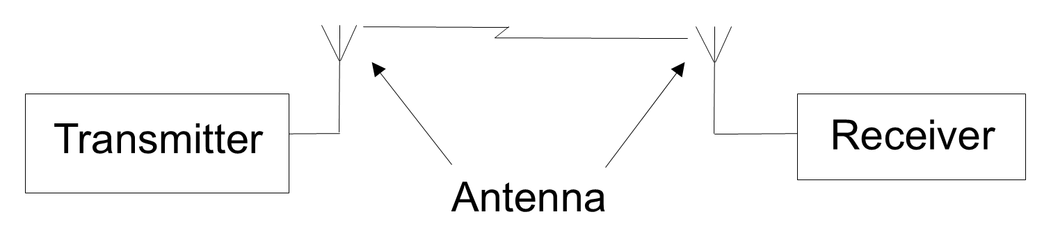
Antennas play a very important part in a communications system, so it is essential to understand the principles on which they operate. While an antenna can be as simple as a piece of wire, more suitable antenna designs are available. Matching the correct antennas to the transmitter and receiver ensures maximum radiated and received powers. In practice, different applications require unique designs, which has led to the design and development of many types of antenna.
Basically, an antenna is any piece of wire carrying an alternating current. A simple way of explaining the process is shown in Figure 12.2, in which electrons move up and down a wire in accordance with the alternating current that changes direction each half cycle (for simplicity, only one electron is shown). As the electrons move up and down the wire, an electric field (E) moves away from the wire—the intensity of the field will vary sinusoidally in proportion to the sinusoidal variation of the alternating current on the wire.
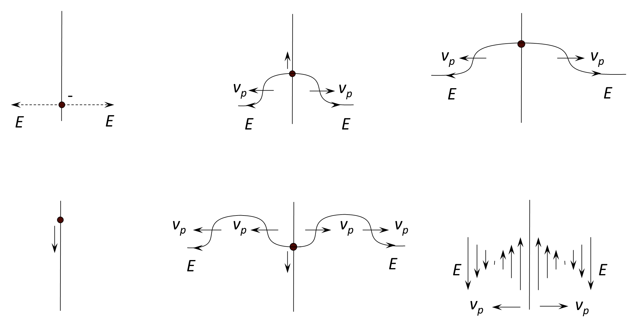
A reasonable physical analogy is that the electron is like a boat moving backwards and forwards in a straight line through the water—the wash of the boat that moves away from the straight line of the boat’s path through the water is similar to the electric field that moves away from the wire.
It should be noted, of course, that there is also a magnetic field (H) associated with the electric field—one cannot exist without the other—but this has been ignored for simplicity in Figure 12.2. For a physical analogy of the magnetic field in relation to the wire, imagine looking end-on down a rod being plunged sinusoidally in and out of a pond of water—the water (magnetic field) will move away from the rod (wire) as a series of concentric waves. So, coming back to our wire, as the alternating current varies in its intensity, the electric field and magnetic fields will move away from the wire in the form of sinusoidally varying waves with the two fields always at right angles to each other.
Back to reading