12.4.1 Radiation Pattern Of Dipoles And Monopoles
Figure 12.11 shows the half-wave dipole, its construction, and its radiation pattern in the principal planes and in three dimensions. The maximum radiation occurs broadside to the dipole, with nulls in the end-fire direction (along the axis). The radiated wave is linearly polarized, with the electric field aligned with the dipole axis.
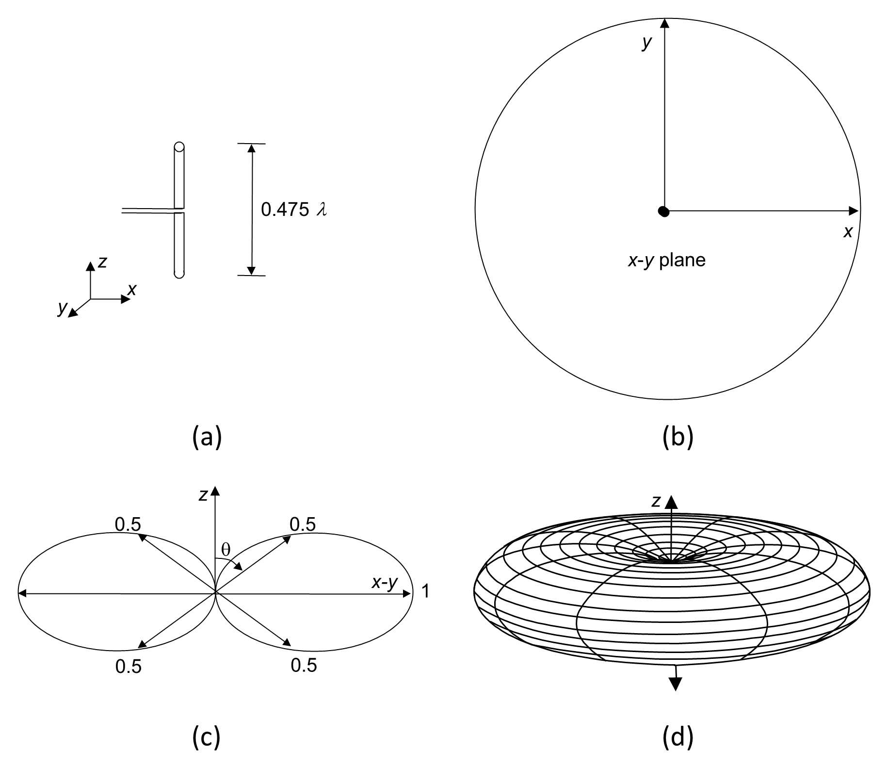
Although termed a half-wave dipole, the physical length required for resonance is slightly less than λ/2. End effects and fringing fields cause the electrical length to exceed the physical length, so practical dipoles are typically cut to approximately 95% of λ/2.
The normalized far-field power pattern of a thin half-wave dipole in free space is:
The radiation pattern is symmetrical about the dipole axis, forming a toroidal shape in three dimensions. Note that the dipole has no radiation in the end-fire direction (along the line of the dipole).
The half-wave dipole has an impedance of 73 Ω; a directive gain of 1.64, (2.15 dBi); an effective aperture of 0.13λ2, and a 3-dB beamwidth of 78°. Because of its well-defined characteristics, the half-wave dipole is often used as a reference antenna, where 0 dBd corresponds to 2.15 dBi.
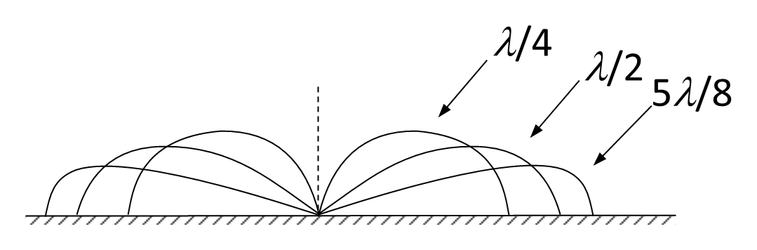
Figure 12.12 illustrates monopole radiation patterns for lengths λ/4, λ/2, and 5 λ/8). The 5λ/8 monopole is sometimes used because it produces a lower take-off angle than the quarter-wave version, which may improve ground-wave or line-of-sight range.
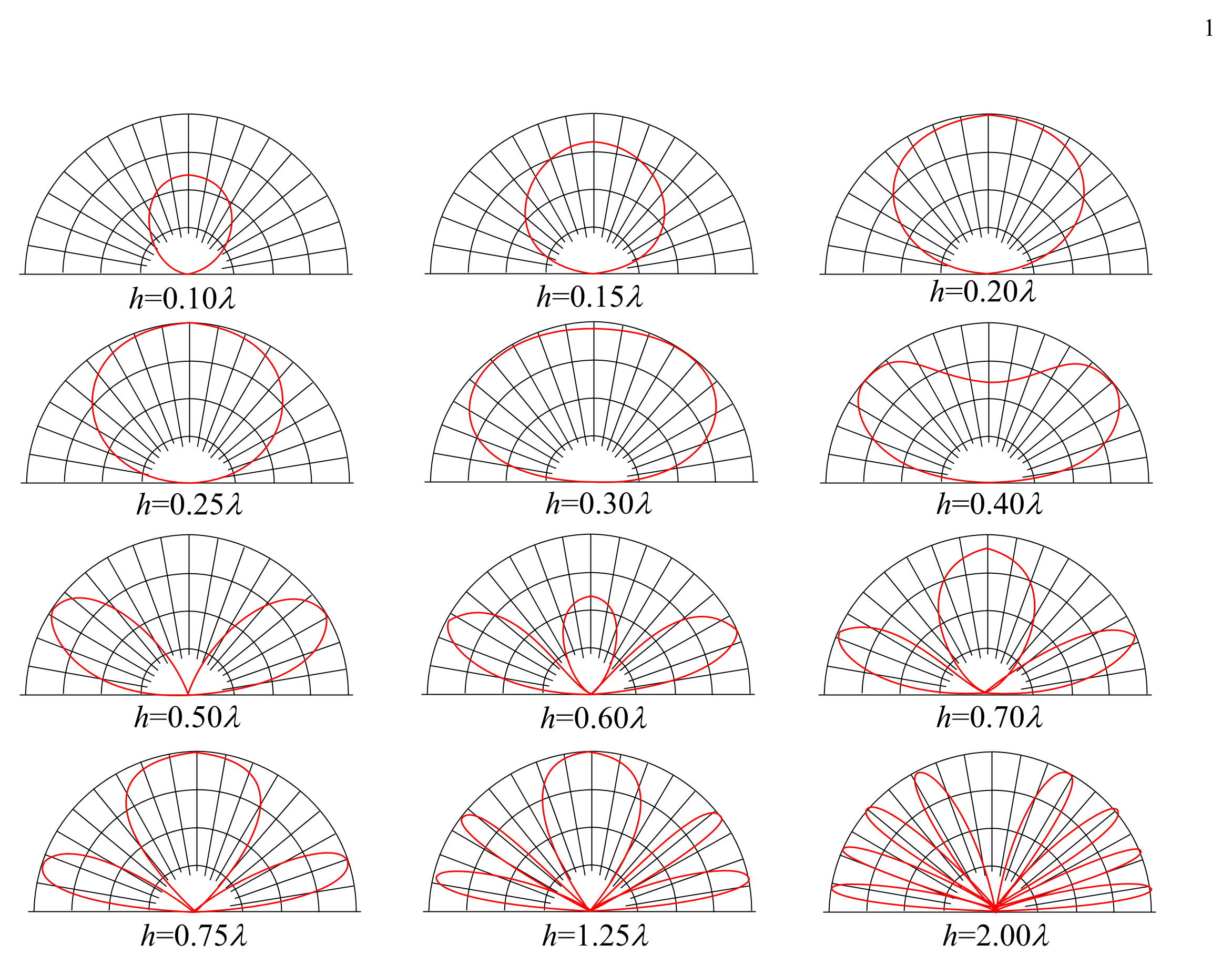
In practice, antennas are rarely in free space. Figure 12.13 demonstrates how the proximity of the ground significantly alters the radiation pattern of a horizontal dipole, particularly as the height above ground changes.