
12.8.9 Array Antennas
An array antenna consists of two or more radiating elements arranged in a deliberate geometrical configuration and excited so that their individual fields combine in space to produce a desired overall radiation pattern. By controlling the relative spacing, lengths, and excitation of the elements, the radiated energy can be reinforced in some directions and suppressed in others. This principle of pattern synthesis allows the designer to increase directivity and gain without increasing transmitter power, simply by redistributing the radiated energy.
In its simplest form, an array may consist of a driven element accompanied by one or more parasitic elements, whose currents are induced electromagnetically rather than fed directly. More complex arrays may employ multiple driven elements with carefully controlled amplitude and phase relationships. The following sections examine several important practical examples of simple arrays, including reflector and director configurations, the Yagi–Uda array, the corner reflector, and the log-periodic antenna. More advanced electronically steered phased arrays are treated separately in Section 12.10.
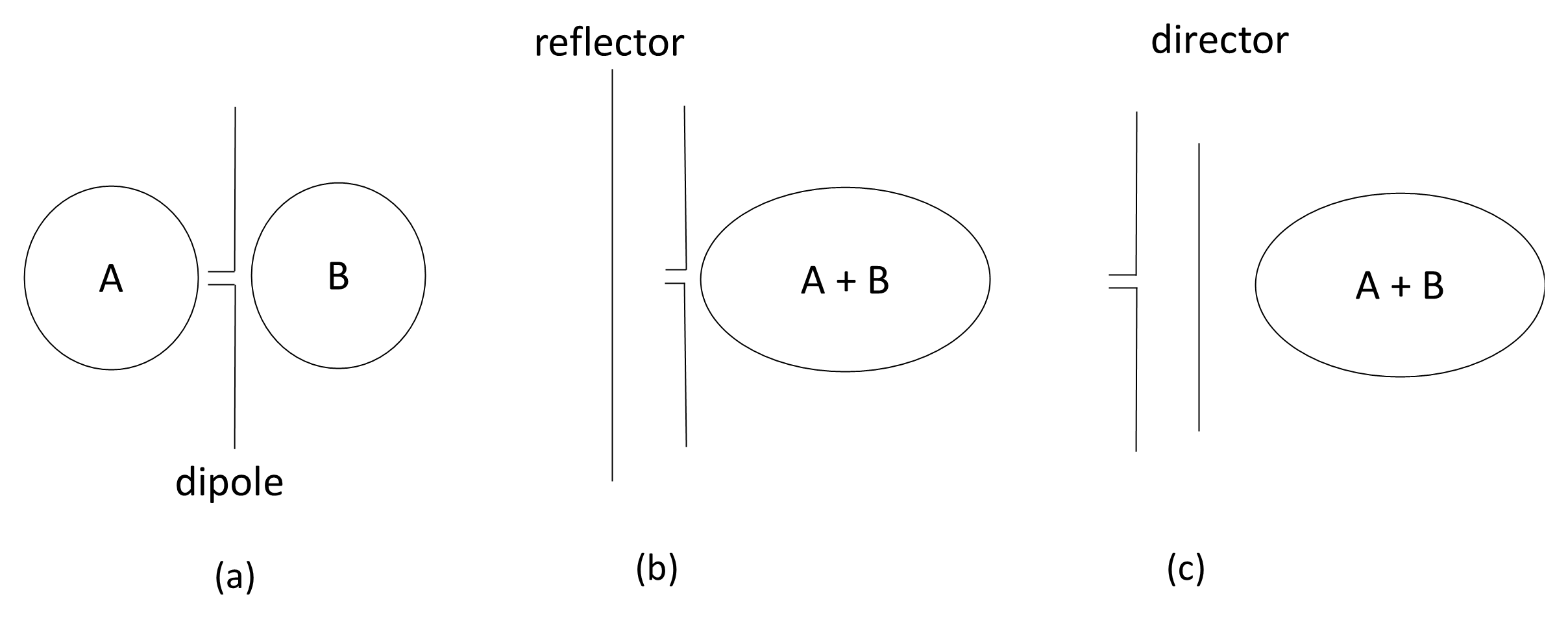
For example, in Figure 12.33(a) we can see that a radiating element has two lobes, A and B. If we redirect lobe A and add it to B, we should double the power radiated in that direction. We can do this by adding a reflector at a suitable distance as illustrated in Figure 12.33(b) or a parasitic director as shown in Figure 12.33(c). The directors and reflectors are located about 0.15 to 0.25λ away from the dipole. Reflectors are slightly longer than the dipole; directors are slightly shorter. Doubling the power gives the antenna twice the gain (relative to a half-wave dipole) or the new antenna has a 3 dB gain over the half-wave dipole. This basic principle underpins the Yagi-Uda antenna.
12.8.9.1 Yagi-Uda Array
As illustrated in Figure 12.34, the Yagi-Uda antenna is a directional array consisting of a single driven half-wave dipole together with one or more parasitic elements mounted collinearly on a common boom. Although the driven element is called so because it is connected to the transmission line, the Yagi-Uda antenna is most commonly used for reception. A reflector element is positioned behind the driven dipole (typically about 0.2λ spacing) and is made slightly longer than the driven element, while one or more directors are placed in front at similar spacings and are made slightly shorter. The reflector re-radiates energy in phase opposition toward the rear, thereby reducing back radiation, while the directors reinforce radiation in the forward direction. The combined mutual coupling between elements causes the energy to be concentrated into a single dominant forward lobe.
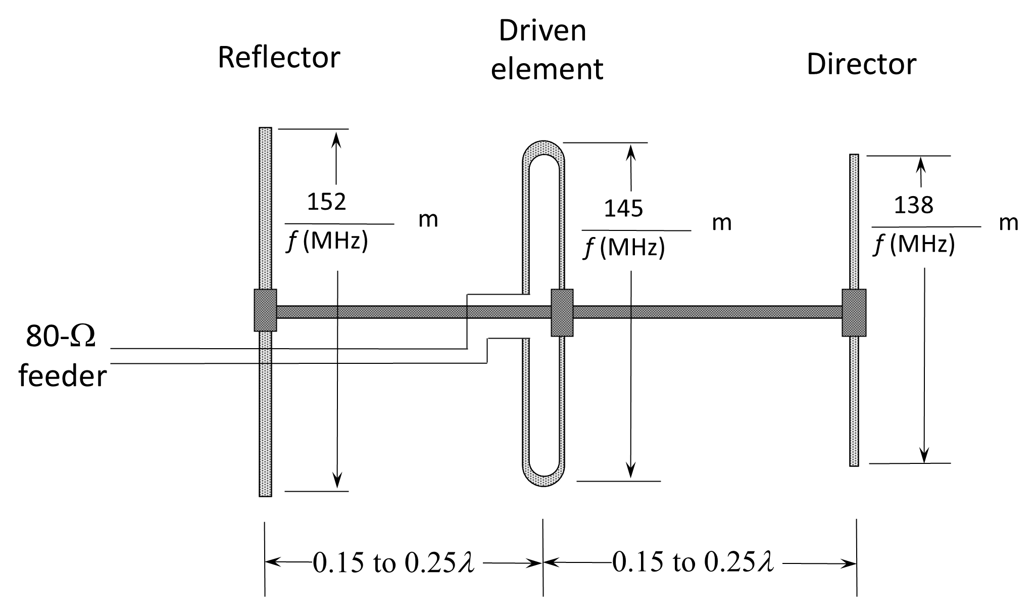
The Yagi–Uda is essentially a narrowband antenna because its performance depends on precise element lengths and spacings relative to wavelength. In practice, it is commonly used over a frequency range of approximately ±2–3% about its design frequency. Within this range it provides substantial forward gain (typically 6–15 dB over a half-wave dipole, depending on the number of directors) and a relatively narrow main beam, often around 30° 3-dB beamwidth for medium-length arrays. As additional directors are added, the forward gain increases and the beamwidth narrows, although with diminishing returns and increased mechanical length. The Yagi–Uda therefore offers an effective compromise between gain, simplicity, and cost, which explains its widespread use in television reception, VHF/UHF communications, and point-to-point line-of-sight links.
In many practical designs, the driven element is implemented as a folded dipole, frequently constructed from tubular conductors rather than thin wire. The folded dipole presents a higher feed impedance (approximately 300 Ω in free space), which, when coupled to the parasitic elements of the array, is transformed to a value that is convenient for matching to balanced feeders or, via a balun, to 50–75 Ω coaxial cable. The tubular construction increases the effective conductor diameter, thereby lowering the antenna Q and modestly broadening the impedance bandwidth. Although the overall Yagi–Uda array remains fundamentally narrowband due to the frequency-sensitive behaviour of its parasitic elements, the use of a folded tubular dipole improves impedance stability, enhances mechanical robustness, and increases power-handling capability. For these reasons, many commercial VHF and UHF Yagi antennas employ a folded tubular dipole as the driven element.
12.8.9.2 Log-Periodic Antenna
Figure 12.35 illustrates a log-periodic antenna, which is a broadband frequency-independent array whose electrical characteristics repeat periodically with the logarithm of frequency (hence the name). Unlike the Yagi–Uda, which is optimized for a narrow band, the log-periodic antenna is designed so that its element lengths and spacings follow a geometric progression. Each successive element is scaled from the previous one by a constant ratio (commonly denoted by τ), and the spacing between elements is similarly scaled. This systematic scaling allows the antenna to operate efficiently over a wide frequency range, often with bandwidth ratios (the ratio of the highest to lowest frequency) of 10:1 or more.
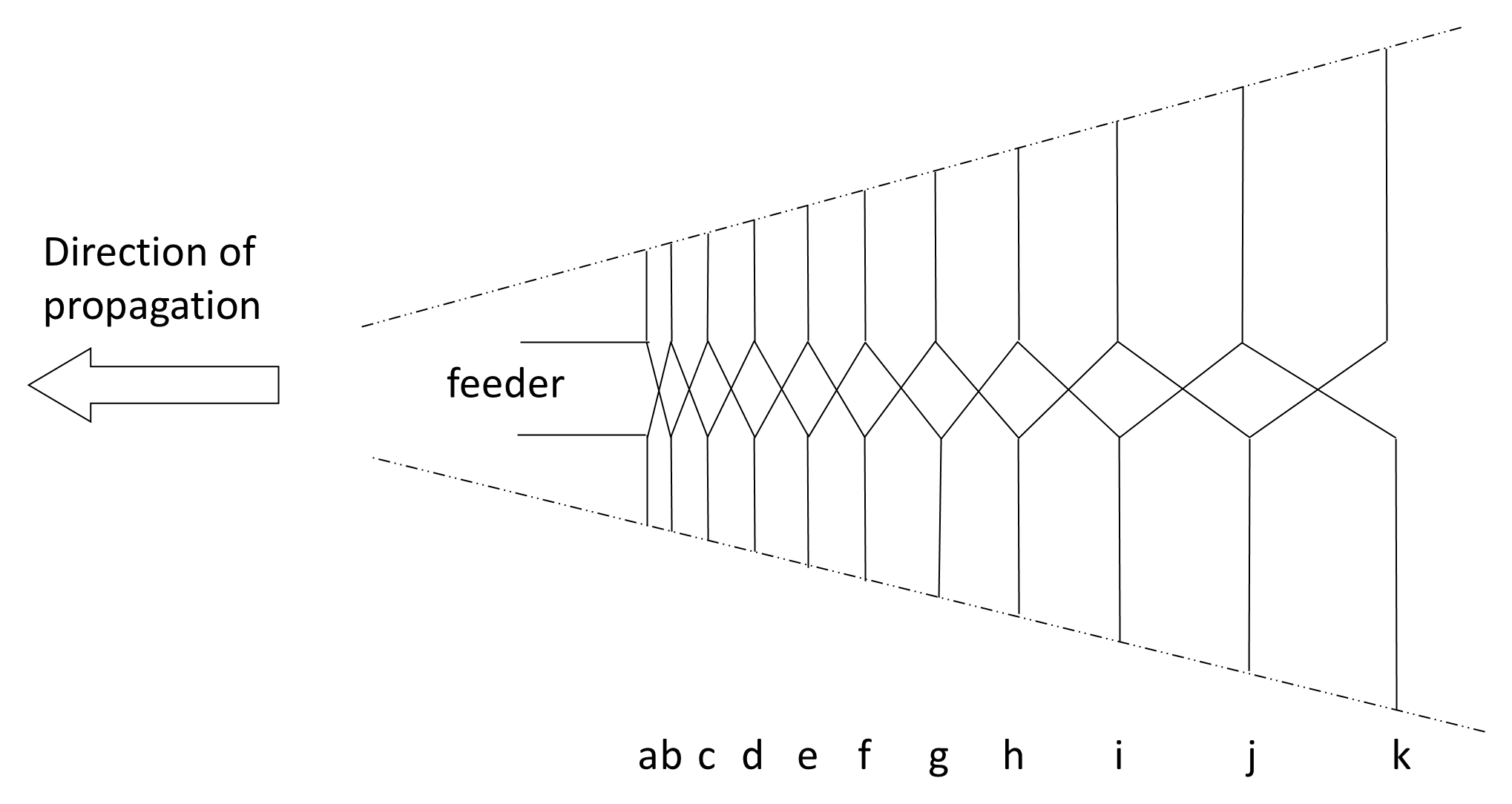
At the lowest frequency of operation, the longest element (k) is approximately half a wavelength long and therefore resonates; elements a to j, being shorter, act primarily as directors. In the middle of the band, an intermediate element (such as h) becomes resonant, with shorter elements acting as directors and longer elements acting as reflectors. At the highest frequency, the shortest element (a) resonates, while the remaining longer elements function as reflectors. Thus, only a small subset of elements near the resonant length at any given frequency actively contributes to radiation. This region is known as the active region of the array, and it effectively shifts along the boom as the operating frequency changes.
The elements are usually fed in an alternating phase arrangement by means of a criss-cross transmission line running along the boom, ensuring that the currents in adjacent elements are 180° out of phase. This feeding arrangement produces a unidirectional radiation pattern with moderate forward gain (typically 6–10 dB over a dipole) and good front-to-back ratio across the design bandwidth. The beamwidth remains relatively stable with frequency, and the input impedance varies only modestly over the operating band, simplifying matching to standard transmission lines.
Because of its wide bandwidth, predictable impedance, and stable radiation characteristics, the log-periodic antenna is widely used in television reception, broadband communication systems, electromagnetic compatibility (EMC) measurements, and surveillance applications. While its gain is generally lower than that of a long Yagi optimized for a single frequency, its principal advantage lies in its ability to maintain consistent performance over a broad frequency range without mechanical or electrical retuning.
Log-periodic antennas should not be regarded as a single antenna type, but rather as a class of frequency-independent arrays defined by a common geometric scaling principle. Numerous structural and electrical variations exist. In terms of frequency coverage, log-periodic designs span a remarkably wide spectrum—from large wire or tubular arrays used in HF skywave communications, through VHF and UHF television and tactical systems, to compact microwave versions employed in EMC testing and specialized SHF applications. Mechanically, they may be constructed from self-supporting rods mounted on a rigid boom, or from wire elements suspended between supporting structures. Electrically, they may be configured for unidirectional or bidirectional operation, and for linear or crossed polarization. This inherent scalability in both physical form and electrical performance gives the log-periodic antenna exceptional flexibility. Its geometry can be adjusted systematically to trade gain, beamwidth, and bandwidth while preserving predictable impedance behavior, making it one of the most adaptable broadband antenna families in practical use.
Back to reading