12.10 PHASED ARRAYS
An increase in gain and directivity can be obtained by arranging two or more antennas in an array with an appropriate regular spacing so that transmitting a phase-shifted carrier from each of the elements of the array causes the radiated fields to reinforce in some directions and destructively interfere in others. The combined radiated field therefore forms a beam with directivity and gain. Additionally, by appropriately selecting the degree of phase shift between array elements, the beam can be oriented in a desired direction, without changing the orientation of the array.
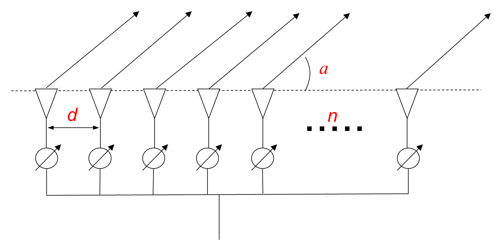
Figure 12-45 illustrates the formation of an array of n elements a distance of d apart. Any antenna can be used as an element of the array, with dipoles, slotted waveguides and helices the most commonly used.
When each element radiates a field E0, the resultant field Er at an angle θ0 to the line of the array is:
where ψ is the phase angle between elements:
The term in brackets in Equation (12.20) is known as the array factor. The maximum value of the array factor is √n for electric fields, which leads to a power gain of n. That is, the gain of the array of n elements is n times the gain of each of the elements.
For an additional phase angle β in the currents driving the antennas, Equation (12.20) becomes:
When β=0, the resultant lobes are at right angles to the line of elements, and the pattern is called a broadside pattern. When β=π, the resultant lobes are along the line of elements, and the pattern is called an end-fire pattern. Broadside patterns tend to be narrower and therefore are used more often.
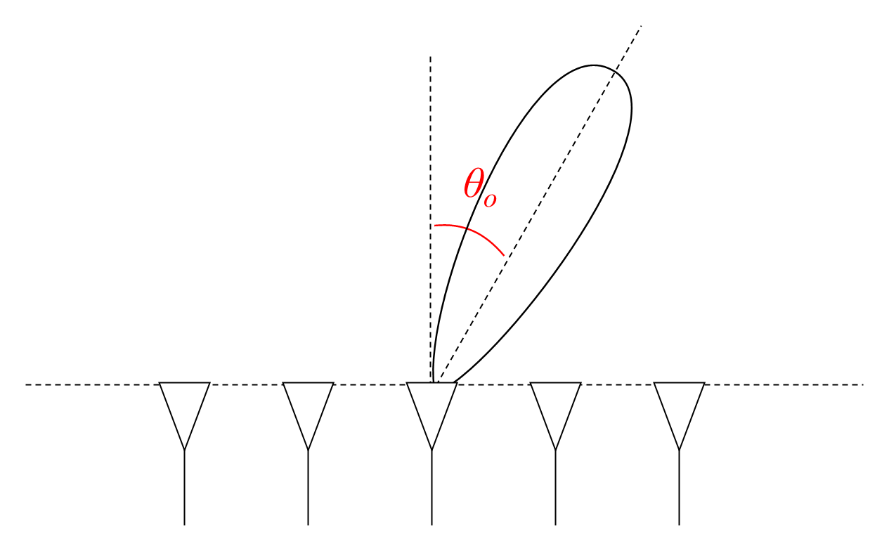
In addition to increased gain, an antenna array can be used to steer the resultant beam by altering the phase difference between adjacent array elements. As illustrated in Figure 12-46, the main beam points at an off-axis angle of θo when the phase difference between elements is:
Consequently, an array can produce a beam in a desired off-axis direction by altering the phase of the fed elements. In addition, the beam can be caused to sweep through a range of angles by appropriately phase-shifting the inputs of the fed elements. The resultant phased arrays are therefore very useful for electronically steering beams from a fixed antenna structure, without the mechanical difficulties associated with rotating the structure, which is useful for antennas for mobile terminals.