
12.8.3 Folded Dipoles
A folded dipole is a balanced, centre-fed antenna consisting of two (or occasionally more) parallel conductors joined together at their ends to form a closed loop. In its simplest and most common form, it comprises two straight, parallel wires of equal length separated by a small, uniform spacing and connected together at both ends. The feed point is applied at the center of one of the conductors, typically through a balanced transmission line or via a balun when fed from coaxial cable. The overall electrical length of the structure is approximately half a wavelength (λ/2) at the design frequency, so its total tip-to-tip length is similar to that of a conventional half-wave dipole. The spacing between the parallel conductors is usually small compared with a wavelength (often a few centimeters at VHF), ensuring that the currents in the two wires remain closely coupled.
In operation, when driven at its center, the applied RF voltage causes current to flow along the driven conductor and, through the end connections, into the parallel conductor. Because the two conductors are closely spaced and electrically connected at both ends, currents are induced in both elements that are nearly equal in magnitude and phase. The structure therefore radiates as a single half-wave dipole, with the familiar toroidal (doughnut-shaped) radiation pattern and maximum radiation broadside to the wire axis. However, the presence of the second conductor modifies the input impedance: for equal-diameter wires, the folded dipole presents an input impedance approximately four times that of a simple half-wave dipole in free space (i.e., about 300 Ω rather than 73 Ω). This impedance transformation property makes the folded dipole especially useful for feeding with 300 Ω twin-lead and for driving Yagi–Uda arrays, where a higher feed impedance is often advantageous.
As illustrated in Figure 12.25, in many practical installations, particularly at VHF and UHF, folded dipoles are constructed from tubular conductors rather than thin wire. Increasing the effective conductor diameter reduces the antenna’s quality factor (Q), thereby broadening its impedance bandwidth and making the resonance less sensitive to small dimensional tolerances. A thicker element stores less reactive energy relative to the radiated energy, producing a flatter impedance-versus-frequency characteristic and improved standing-wave ratio (SWR) performance over a wider band. This is especially advantageous in broadcast arrays and broadband systems, where stable impedance and predictable matching are required.
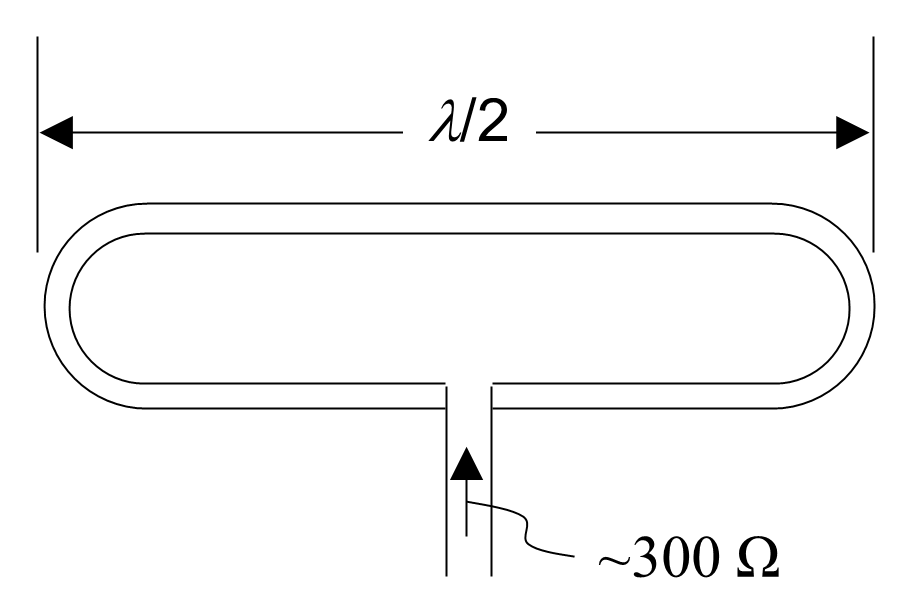
Tubular construction also provides substantial mechanical and thermal benefits. Aluminium or copper tubing offers greater rigidity and resistance to wind loading, vibration, and environmental degradation than wire, ensuring long-term dimensional stability when mounted on towers or exposed structures. The larger conductor cross-section reduces current density and ohmic loss, thereby improving efficiency and power-handling capability—an important consideration in high-power transmitters. For these electrical and structural reasons, tubular folded dipoles are widely used in professional and broadcast applications.
Back to reading