
12.4 THE DIPOLE AND MONOPOLE
When we discussed balanced transmission lines in Chapter 10, we saw that electromagnetic energy is largely confined between the conductors and reflects from an open or short circuit at the end of the line. The question now is how to launch that energy efficiently into free space so that it is radiated rather than reflected back toward the transmitter.
A useful question is why two wires carrying alternating current can radiate, whereas a properly terminated transmission line does not. In a transmission line, equal and opposite currents flow in close proximity, and their fields are largely confined between the conductors. If the ends of the line are opened out, as shown in Figure 12.9(a), the currents are no longer confined. Time-varying electric and magnetic fields are then free to detach from the structure and propagate as electromagnetic waves. The two opened conductors form a radiating element known as the dipole (or Hertzian antenna). Understanding its operation is fundamental, as many practical antennas are derived from it.
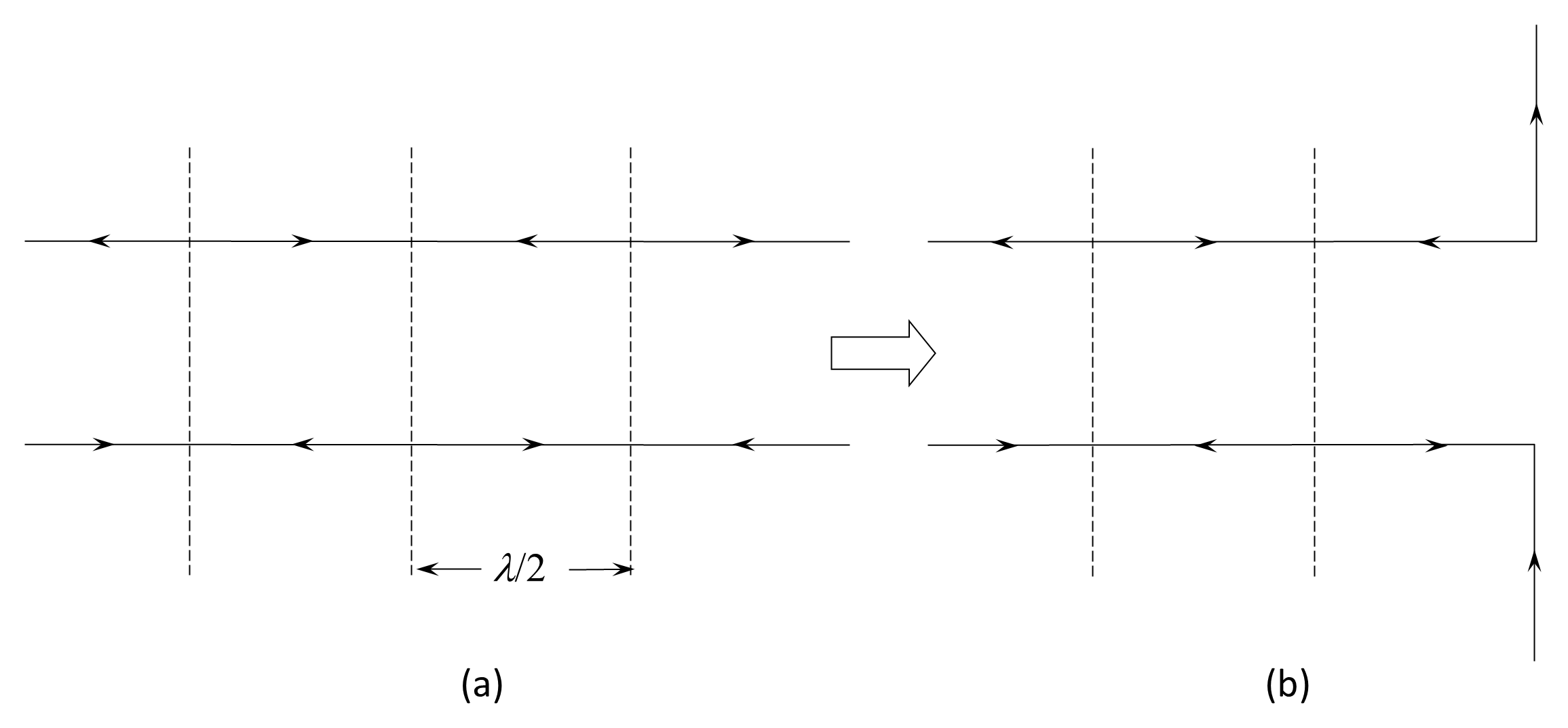
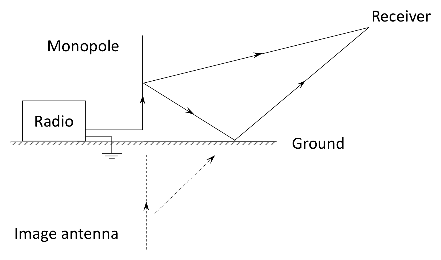
In many applications a shorter antenna is desirable, particularly for mobile or field deployment. A monopole (or Marconi antenna) is effectively half a dipole, with the other half provided by an image formed by induced currents in the ground. Under the assumption of a perfectly conducting infinite ground plane, the tangential electric field at the surface is zero, forcing an equal and opposite image current beneath the plane. The resulting radiation above the ground is therefore identical to that of a complete dipole in free space. The monopole thus provides the deployment advantage of being half the physical length of the equivalent dipole.
Figure 12.10 illustrates the equivalence between a quarter-wave monopole over a perfectly conducting ground plane and a half-wave dipole. In practice, however, the Earth is not a perfect conductor. It has finite conductivity and permittivity, both of which vary with moisture and mineral content. This finite conductivity introduces a ground-loss resistance, reducing the effectiveness of the image current and modifying the radiation pattern. In addition, energy dissipated in the ground reduces overall antenna efficiency.
If the Earth conductivity is poor, performance may be improved by using a counterpoise or Earth mat. An Earth mat typically consists of radial copper conductors extending at least a quarter-wavelength (preferably half-wavelength) from the antenna base, forming an artificial ground plane. The mast base is insulated from the Earth, and the feeder is connected between the antenna base and the counterpoise. If the monopole itself is elevated, an artificial ground plane must be elevated with it.
Back to reading