12.9.2 The Parabolic Reflector
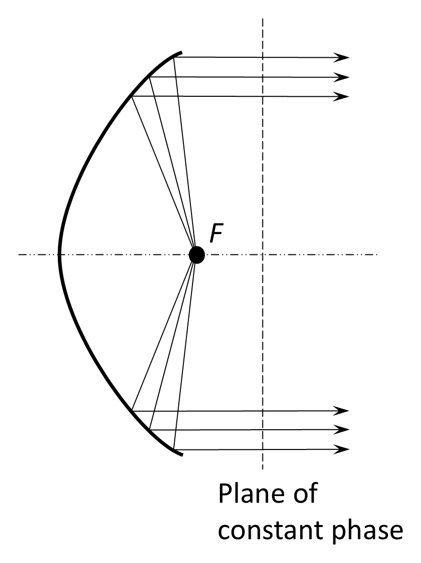
Parabolic reflectors are widely used at UHF/SHF because they provide high gain and low side lobes. The reflectors act for RF in a similar manner to reflective mirrors at light frequencies. A parabolic surface is defined by the equation y2=4fx where y is any point of the surface, x is the corresponding abscissa, and f is the focal length of the parabolic surface. The nature of a parabolic surface is such that a ray generated at the focus reflects from the surface and passes through another focus located at infinity. Consequently, a diverging wavefront emanating from a feed point at the focus of the parabola is converted into a parallel wavefront at any point past the focus in a plane parallel to the parabolic aperture. This property of focusing that is usually associated with light rays, mirrors and lenses, can equally be applied to parabolic reflectors at microwave frequencies. This process is illustrated in Figure 12.37 where, at any plane past the focus, all rays have travelled the same distance and therefore have the same phase. The result is a highly focused beam with narrow beam width.
In practical antennas, some energy diffracts over the side of the aperture resulting in sidelobes. There can be many sidelobes, depending on the size of the reflector. For example, for a large dish, there may be thousands of sidelobes, each about one-tenth of a degree; for a small dish there may be several hundred sidelobes, each one or two degrees wide.
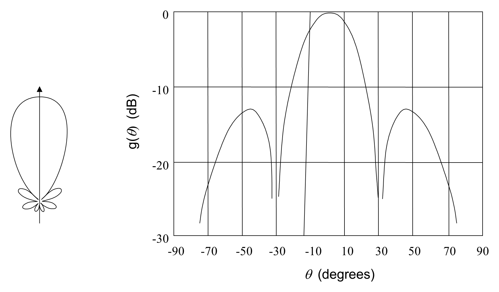
A typical radiation pattern for the parabolic reflector is shown in Figure 12-38. There is a main lobe and a number of sidelobes. The pattern has a 2J1(ψ)/ψ distribution where J1(ψ) is a first-order Bessel function and ψ=πDsinθ/λ.
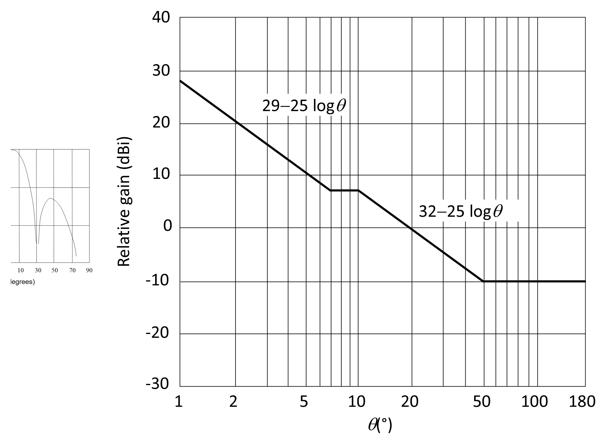
In practice the sidelobes are accounted for by an envelope function. Reference radiation patterns are prescribed by the ITU to dictate the appropriate level of sidelobes. For example, Figure 12-39 illustrates the following reference radiation pattern:
There can be many sidelobes, depending on the size of the reflector. For example, for a large dish, there may be thousands of sidelobes, each about one-tenth of a degree; for a small dish there may be several hundred sidelobes, each one or two degrees wide.
The overall efficiency of a parabolic reflector antenna, η, is determined by several contributing factors. These efficiencies are typically multiplicative, so that the total antenna efficiency may be expressed as the product of the individual components:
- Aperture illumination efficiency (ηa). Accounts for non-uniform amplitude and phase distribution across the reflector aperture. Uniform illumination maximizes directivity but may increase spillover; tapered illumination reduces sidelobes but slightly lowers gain.
- Blockage efficiency (ηb). Represents loss due to obstruction of the main reflector aperture by feed horns, sub-reflectors, and support structures. Blockage reduces effective aperture area and increases sidelobe levels.
- Spillover efficiency (ηs). Accounts for feed energy that does not intercept the reflector surface and instead radiates beyond it. Spillover reduces useful gain and may increase system noise temperature.
- Polarization (cross-polarization) efficiency (ηp). Represents loss due to power coupled into the undesired orthogonal polarization or due to polarization mismatch between transmitting and receiving antennas.
- Surface (Ruze) efficiency (ηr). Represents loss in gain caused by surface deviations from the ideal parabolic shape. Surface roughness introduces phase errors across the aperture, reducing coherent addition of the reflected fields. This effect becomes more severe as wavelength decreases.
- Ohmic and mismatch efficiency (ηi). Accounts for resistive losses in conductors and for power reflected due to impedance mismatch between the antenna feed and the transmission line. Mismatch loss is typically quantified using VSWR or reflection coefficient.
- Phase efficiency (ηϕ). Accounts for phase errors across the aperture caused by feed displacement, reflector distortion, or alignment errors. These errors reduce effective gain even when amplitude illumination is uniform.
The combination of these factors normally results in an overall efficiency, η, of between 50–60% for smaller dishes to 65–75% for larger well-engineered reflectors. Foldable antennas have an efficiency of the order of 45%.
It should be noted that, in general, it is desirable to improve each of the above contributions to efficiency in order to improve the overall efficiency of an antenna. However, improvement in one component may well adversely affect improvement in another. For example, uniform illumination will improve aperture efficiency, ηa, but will create spillover, whereas spillover efficiency, ηs, would be improved if the illumination was tapered toward the edge of the antenna. Tapering the beam not only adversely affects the uniformity of illumination but will also decrease blockage efficiency, ηb, since more power is then being blocked. In practice, the best compromise is achieved by controlling the edge illumination.
The gain of a parabolic reflector with a circular aperture of diameter D is:
The half-power beamwidth of a parabolic reflector antenna depends on the distribution of the electromagnetic fields across the aperture such that:
where k has a value typically between 1.1 and 1.4.
Equation (12.15) describes the maximum gain—that is, the value of the gain function along the antenna boresight. For small off-boresight angles, θ, the gain can be approximated by:
Figure 12-40 shows that there are a number of different ways to feed a parabolic reflector. The antenna can be fed at the focus by a dipole from behind, at the focus with a horn antenna fed by a waveguide, and from behind through a horn with reflection from a sub-reflector at the focus.
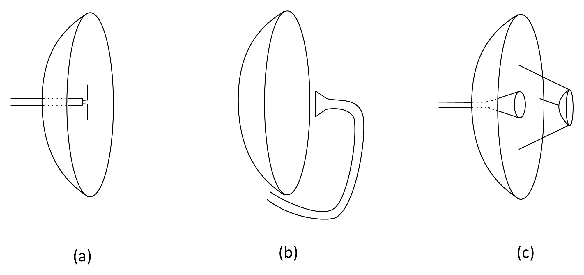
When fed from the focal point, a parabolic reflector produces a circularly symmetric radiation pattern, as shown in Figure 12.37. When alternative feed arrangements are used—either front-fed or rear-fed via a sub-reflector—the gain, 3-dB beamwidth, and sidelobe levels depend on how the feed illuminates the reflector aperture. The amplitude and phase distribution across the reflector surface strongly influence overall efficiency and pattern shape.
When fed from the front with a waveguide and horn, there are significant additional losses due to the additional attenuation in the waveguide and the larger noise that results from the feed horn looking directly at the relatively hot Earth. Consequently, such feed arrangements are only used in small Earth stations where simplicity drives cost. In larger Earth stations, where it is very desirable to keep waveguide lengths to a minimum to reduce attenuation and noise, the most suitable feed is from the rear via a sub-reflector. The double-reflector arrangement provides for a more robust feed arrangement, especially when a steerable antenna is required.
In a simple front-fed configuration, a waveguide and feed horn are located at or near the focus of the reflector. While mechanically straightforward, this arrangement may introduce additional losses due to feed-line attenuation and may increase noise pickup, depending on the direction in which the feed radiates. For larger or higher-frequency systems, minimizing feed-line length can be advantageous, and this has led to the widespread use of rear-fed double-reflector arrangements.
In double-reflector systems, a smaller sub-reflector is positioned near the focus of the main parabolic reflector. This allows the primary feed to be located behind the main reflector, reducing feed-line length and improving mechanical robustness, particularly in steerable antennas. Because the sub-reflector is typically smaller than a direct-feed horn, blockage of the main aperture can be reduced compared with some front-fed configurations.
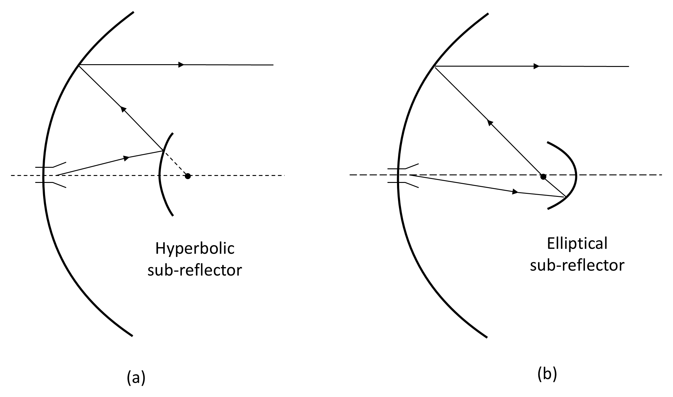
Figure 12-41 illustrates the two main types of double-reflector feed systems which are named after the astronomers who first developed them:
- Cassegrain. The sub-reflector is a hyperboloid with two focal points: one coincides with the focus of the main parabolic reflector, and the other coincides with the phase center of the feed antenna.
- Gregorian. The sub-reflector is an ellipsoid, with one focal point at the focus of the main reflector and the other at the phase center of the feed.
These configurations are widely used in radar, radio astronomy, terrestrial microwave links, and other high-gain antenna systems.
When the feed is located along the axis of the main reflector—whether directly or via a sub-reflector—the antenna is described as center-fed (see Figure 12-40). A limitation of center-fed systems is aperture blockage caused by the feed, support structures, or sub-reflector. Blockage reduces effective aperture area, lowers efficiency (often by several percent), and may increase sidelobe levels due to scattering.
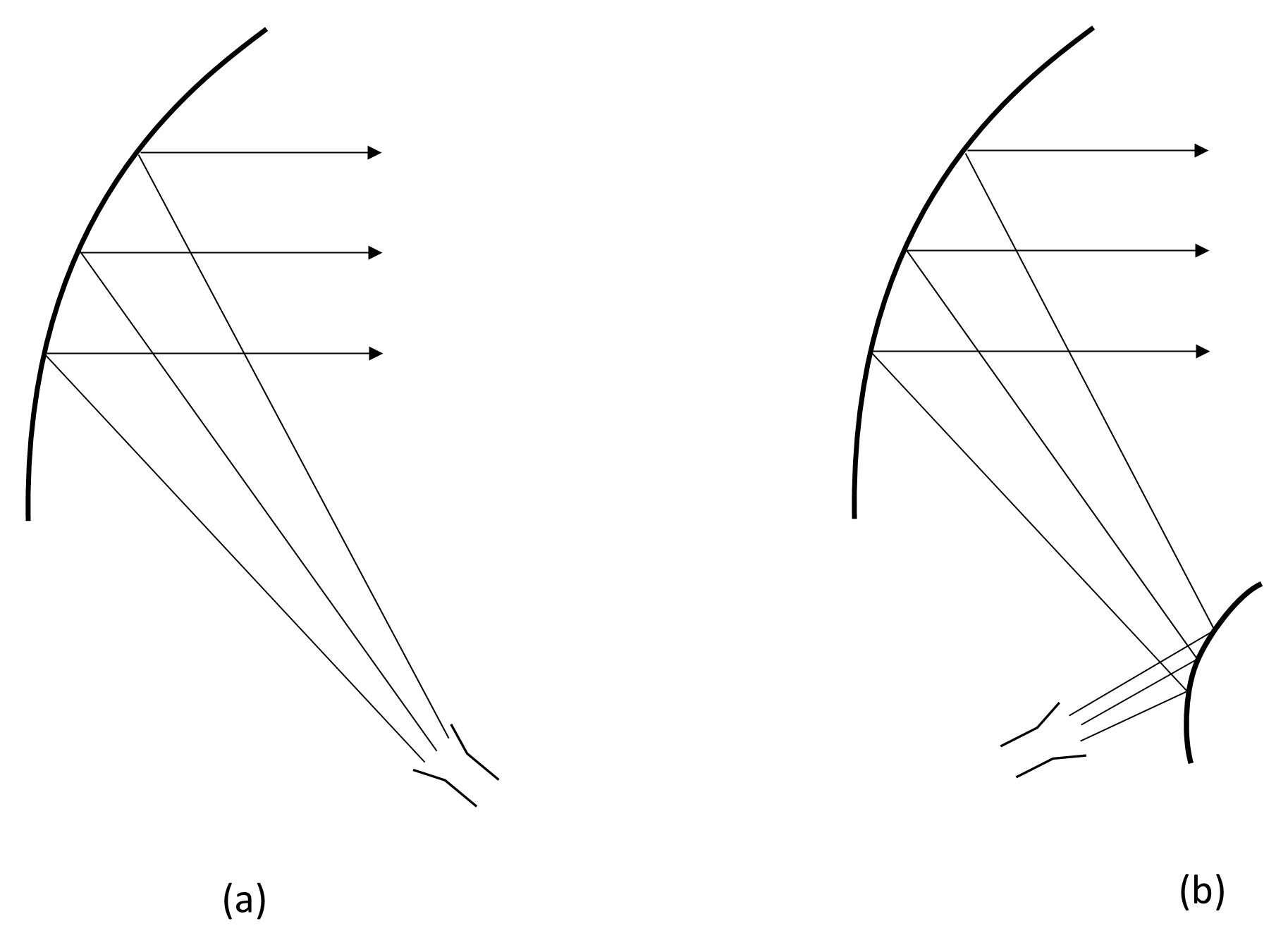
To mitigate these effects, an offset-feed configuration may be used. Figure 12-42 illustrates offset-feed arrangements for direct feed and feed via a sub-reflector. In this arrangement, the reflector is a section of a larger paraboloid, and the feed is positioned off-axis so that no structure obstructs the main beam. Offset-feed designs reduce blockage and generally improve aperture efficiency. However, because the geometry is asymmetric, the main beam may exhibit slight distortion and increased cross-polarization. Additionally, offset reflectors are more complex mechanically and may require stronger structural support to maintain surface accuracy.
Offset configurations are widely used in communication, radar, and broadcast applications, particularly for moderate-sized reflectors. Well-designed offset systems can achieve aperture efficiencies approaching 70–75%.
Further improvements in efficiency can be achieved by reflector shaping. Rather than using purely geometric conic sections, modern reflector surfaces may be optimized using computational design techniques to tailor the illumination distribution, reduce spillover, suppress sidelobes, and improve polarization performance. Advances in computer-aided design and manufacturing have made such shaped-reflector systems practical across a wide range of communication and sensing applications.