
12.8.8 Elevated Antennas
As discussed in Chapter 11, when an antenna is located at or near ground level, the maximum useful range of terrestrial RF communication is constrained by the geometric radio horizon. Increasing antenna height extends the line-of-sight distance and reduces ground absorption and diffraction losses. Elevation therefore improves coverage range, reduces multipath fading in many environments, and can significantly alter the radiation pattern due to changes in ground interaction.
12.8.8.1 Elevated Dipole
When a half-wave dipole is elevated above ground, the analysis is relatively straightforward because the dipole is already a balanced radiator. As discussed in Section 12.4.1, the ground primarily influences the radiation pattern through image formation and reflection effects. At heights of approximately 0.5λ or greater, the dipole begins to develop a lower-angle main lobe, improving long-range performance. As height increases further, multiple lobes appear in the vertical plane due to constructive and destructive interference between the direct and ground-reflected waves. Thus, dipole height is often selected to optimize the take-off angle appropriate for the intended mode of propagation (e.g., low angles for long-distance VHF/UHF line-of-sight links, or higher angles for certain HF skywave applications).
12.8.8.2 Elevated Monopole
When a grounded vertical monopole is used at ground level, the Earth forms part of the radiating system by acting as an image plane. In effect, a quarter-wave monopole over a conducting ground behaves as a half-wave dipole due to the formation of an image current below the surface. When the monopole is elevated above ground, however, the natural conducting plane is no longer immediately beneath the radiator. The Earth is now separated from the antenna by a finite distance, and its image-forming effect is reduced. Consequently, the radiation pattern, feed impedance, and efficiency are altered. The simple quarter-wave monopole assumption no longer strictly applies.
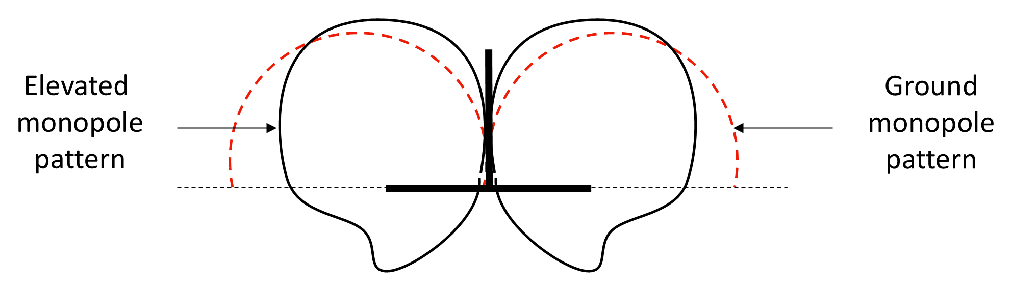
To preserve the intended radiation characteristics, an artificial ground plane is introduced at the base of the elevated monopole. This elevated ground plane provides a local reference conductor that approximates the missing image plane. In its simplest form, this may consist of several radial conductors extending horizontally from the feed point. Because the artificial ground plane has finite size, the current distribution is not identical to that of an infinite conducting surface. As illustrated in Figure 12.30, the resulting radiation pattern may be distorted compared with that of a true quarter-wave monopole over ground. In particular the elevation pattern may tilt upward, the radiation resistance may change, and the feed impedance may deviate from the nominal 36–40 Ω of a ground-mounted quarter-wave monopole.
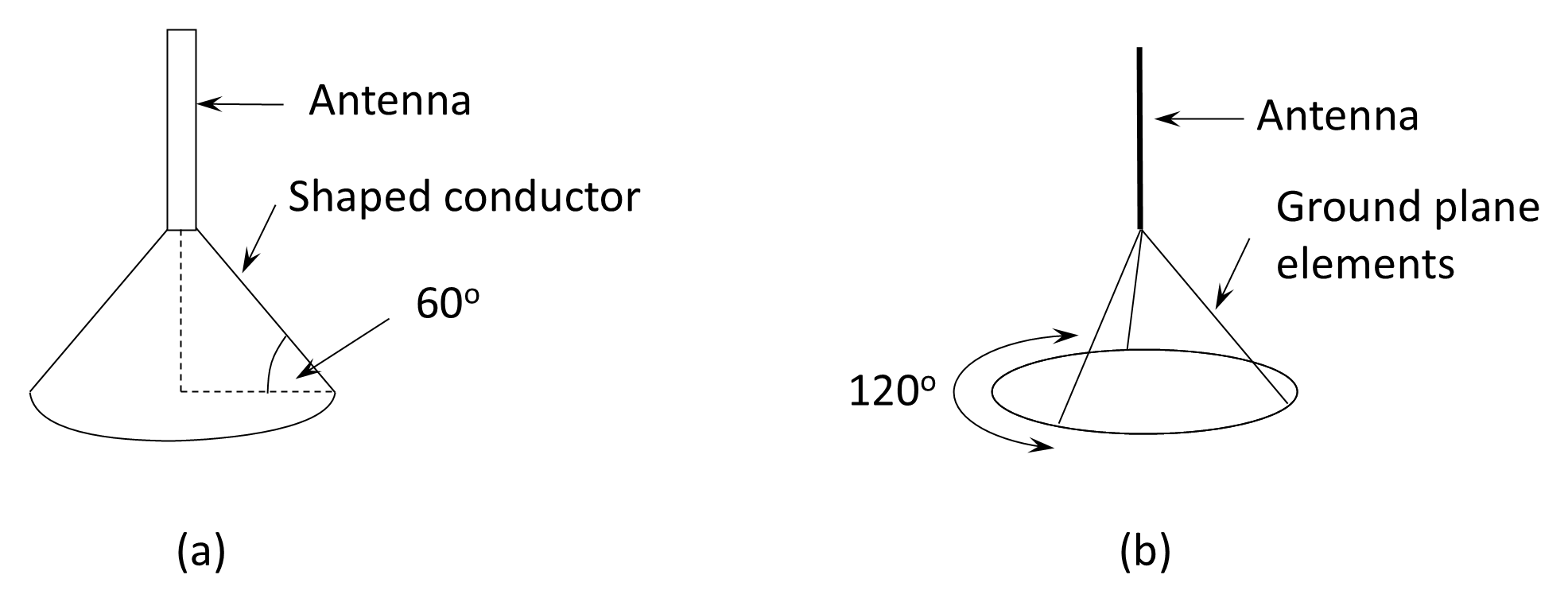
To restore a more symmetrical and predictable radiation pattern, the flat elevated ground plane can be shaped into a downward-sloping cone, as illustrated in Figure 12.31. The conical ground plane improves current distribution and stabilizes impedance. A practical approximation of the conical surface may be achieved using three or four wires spaced evenly (e.g., at 120° intervals), as shown in Figure 12.31(b), although some reduction in efficiency may occur compared with a solid surface.
The elevated ground plane serves several important functions. It reduces ground-loss resistance, particularly at VHF where soil conductivity may be poor. It suppresses unwanted current flow on the supporting mast, which would otherwise distort the pattern and introduce high-angle radiation. Finally, it provides a convenient means of impedance adjustment; by varying the slope angle of the radials, the feed impedance can be increased toward 50 Ω, facilitating direct coaxial connection without additional matching networks.
In summary, elevating a monopole requires recreating the electrical function of the Earth through an artificial ground plane. Proper design of this elevated reference conductor is essential to preserve radiation efficiency, pattern symmetry, and impedance characteristics comparable to those of a ground-mounted quarter-wave vertical.
12.8.8.3 Discone
The discone antenna is a further development of the elevated ground-plane concept in which the single vertical monopole is replaced by a circular disc positioned above a conical conducting surface, as shown in Figure 12.32). The disc forms the upper capacitive element, while the cone functions as a broadband ground plane. Together they form a structure whose impedance varies only gradually with frequency, giving the antenna its characteristic wideband performance.
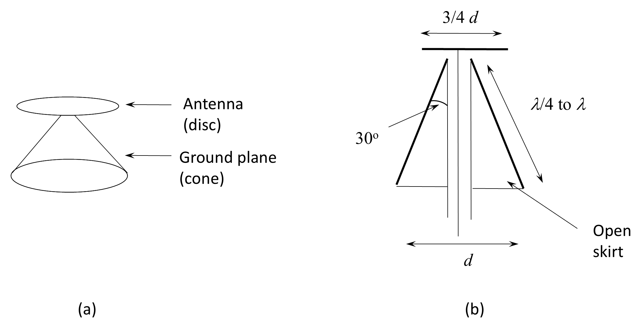
Unlike a quarter-wave monopole, which is inherently resonant and therefore narrowband, the discone operates as a non-resonant radiator. The disc-to-cone geometry provides a smooth transition of current distribution over a wide frequency range, resulting in a low and relatively stable VSWR—typically below 2:1—across bandwidth ratios of 5:1 to 10:1 or more, depending on design proportions. For this reason, discones are often described as ultra-wideband VHF/UHF antennas.
The lower frequency limit is determined primarily by the diameter of the cone (approximately corresponding to a quarter wavelength at the lowest operating frequency), while the upper frequency limit is governed by the disc diameter and mechanical dimensions. Practical discone antennas commonly cover ranges such as 100–500 MHz or 25–1300 MHz in scanning and monitoring applications.
The radiation pattern is broadly omnidirectional in the horizontal plane, similar to that of a vertical monopole, with maximum radiation near the horizon. As frequency increases, some minor pattern distortion and lobe formation may occur, but the antenna generally maintains useful omnidirectional coverage over its operating band. Polarization is predominantly vertical, making the discone suitable for terrestrial VHF and UHF communication systems.
For weight reduction and wind loading considerations, both the disc and cone may be constructed from radial wires rather than solid metal surfaces, with minimal impact on performance provided that the radial spacing is electrically small compared with the wavelength.
Because of its broadband impedance characteristics, the discone is typically fed directly with 50 Ω coaxial cable, without the need for additional matching networks. Its principal advantages are: very wide bandwidth; low and stable VSWR, omnidirectional coverage, and mechanical simplicity. Its limitations include relatively modest gain (typically comparable to or slightly above that of a simple vertical monopole, around 0–2 dBi) and limited suitability for high-power transmission unless robustly constructed.
In summary, the discone antenna provides a practical solution where wide frequency coverage and consistent impedance are more important than high gain, and it is therefore widely used in monitoring, scanning receivers, broadband communication systems, and test installations.
Back to reading