12.8.5 Corner Reflector
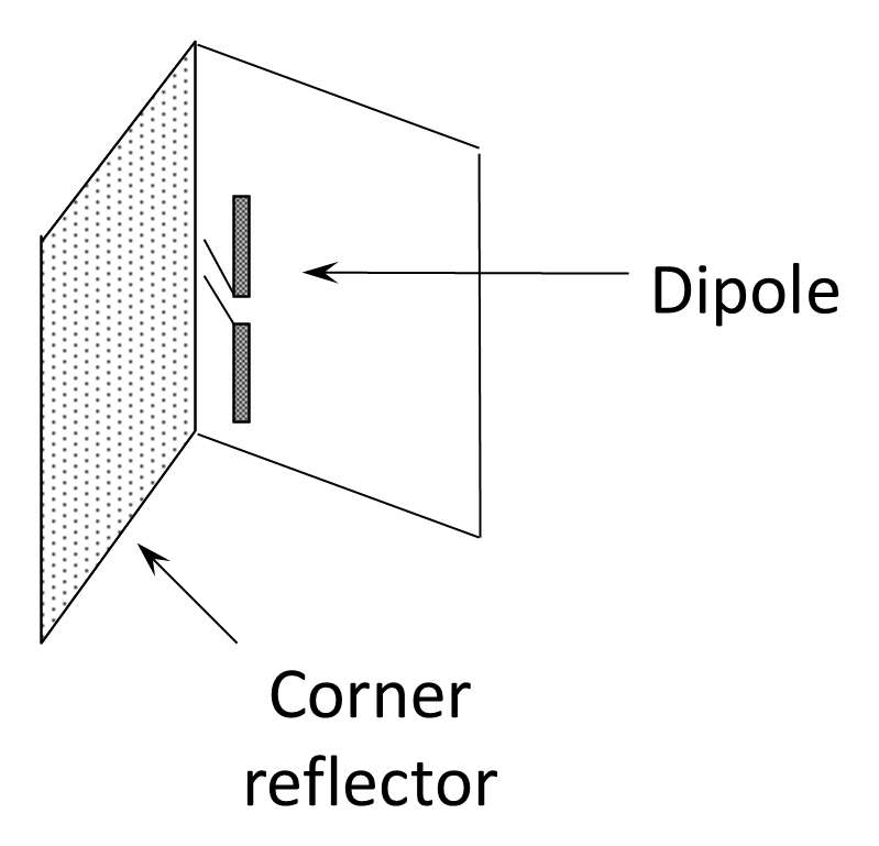
The corner-reflector antenna may be constructed in the VHF range, particularly upper VHF. It is predominantly used for line-of-sight radio relay links and, as illustrated in Figure 12.27, consists of a normal half-wave dipole positioned in front of two conducting planes arranged at an angle (commonly 90°), forming a “corner” reflector. The reflector surfaces act as mirrors, producing image currents that reinforce radiation in the forward direction while suppressing radiation to the rear. The antenna has a radiation pattern broadly similar to that of a Yagi–Uda array, with an average gain of about 9 dB over a half-wave dipole.
The driven dipole is typically placed approximately 0.2–0.3λ in front of the vertex of the corner, where constructive interference between the direct radiation and the reflected fields produces a strong forward beam. The included angle between the reflector panels influences both gain and beamwidth: a 90° corner is common, but smaller angles can increase directivity at the expense of mechanical size and pattern stability. Compared with a multi-element Yagi, the corner reflector achieves comparable gain with a simpler structure and without the need for precisely tuned parasitic directors. It also tends to exhibit slightly broader bandwidth and improved front-to-back ratio due to the large reflecting surfaces.
Mechanically, the reflector may be constructed from sheet metal or wire mesh, the latter being sufficient provided the mesh spacing is small relative to the wavelength. Because of its structural simplicity, moderate gain, and good directional characteristics, the corner-reflector antenna has been widely used in fixed VHF and UHF links, television reception, and point-to-point communication systems where ruggedness and predictable performance are required.