
12.5 TRAVELLING WAVE ANTENNAS
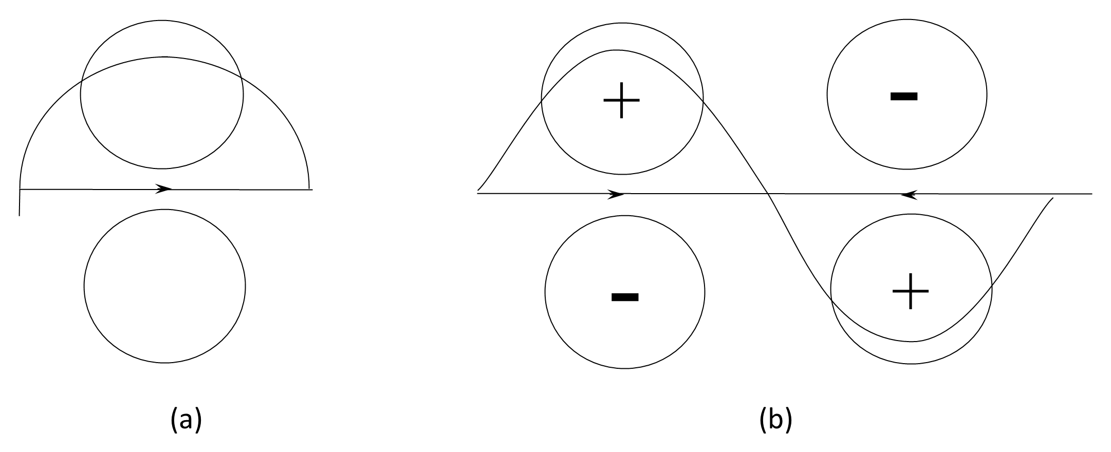
So far, we have discussed center-fed dipoles and monopoles, which are generically called resonant antennas. Figure 12.19(a) shows that an end-fed half-wavelength antenna has the same radiation pattern as a half-wave monopole. Figure 12.19(b) illustrates the pattern that results if we increase the length of the end-fed antenna to a full wavelength.
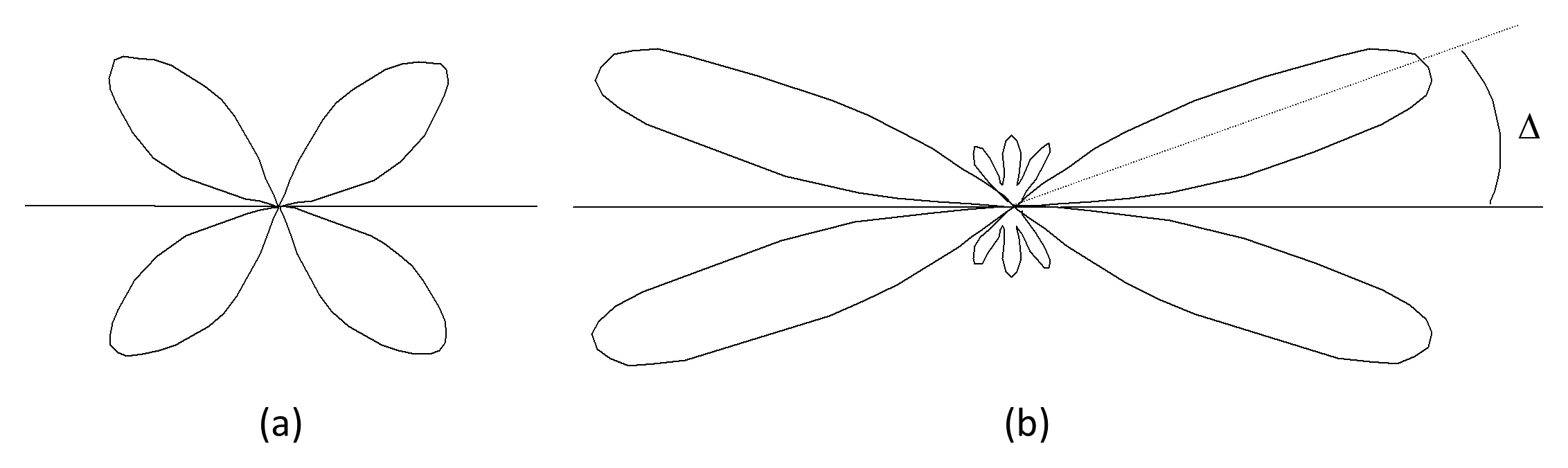
Each half-wavelength section has a radiation pattern, but because of the reversal of current, the two are out of phase and add to get the total pattern illustrated in Figure 12.20(a). Figure 12.20(b) shows the polar diagram for a wire 6λ long. As the wire is increased in length, the main lobes become larger and are closer to the wire (that is, the angle Δ is smaller).
If we now terminate the wire in a resistance equal to the characteristic impedance of the wire, there is no longer a standing wave on the antenna and the lobes A and B shown in Figure 12.21(a) disappear, as illustrated in Figure 2.26(b).
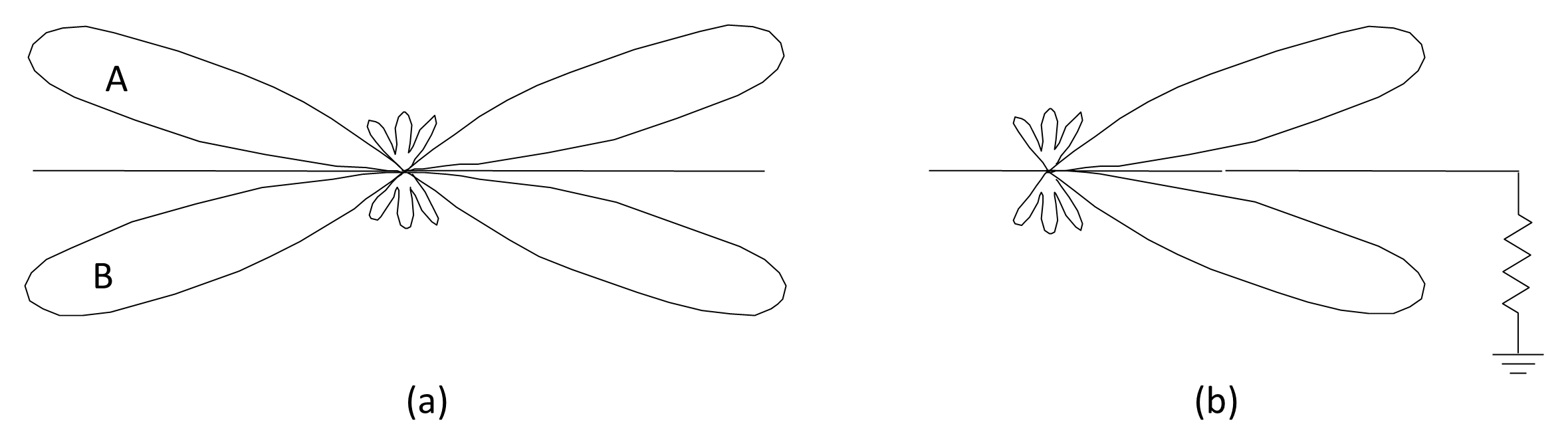
Now we have a directional antenna, the three-dimensional polar diagram of which looks like an obese ice-cream cornet coaxial with the wire. Since the antenna is no longer resonant, its impedance (about 300 Ω) is more stable than a resonant dipole. The size of the main lobes, and the angle Δ will change with frequency if the length remains fixed so the antenna is not truly broadband.
A single long terminated wire is not often used as an antenna by itself but is an essential element of a number of more complex antennas that we discuss in the following sections.
Back to reading