
12.3.7 Antenna Impedance
We saw in Chapter 10 that a transmission line has a characteristic impedance and we also saw that, to avoid any reflections from the end of the line (that is, to make the line look infinitely long), we need to terminate the line with an antenna that has an impedance equal to the characteristic impedance of the transmission line. Remember that impedance comprises resistance (R), and/or capacitance (C), and/or inductance (L), and that the characteristic impedance of a transmission line is purely resistive.
The impedance of an antenna depends mainly on its electrical dimensions and there will be naturally resistive, capacitive, and inductive components in the impedance of any real antenna. Capacitances and inductances are undesirable because they disrupt the flow of energy, so the first step in creating an efficient antenna is to ensure that its impedance is a pure resistance. The second step is to make sure that the resistance is the same as the characteristic impedance of the transmission line (and hence the output impedance of the transmitter, or input resistance of the receiver) to which it is connected. If the output impedance of the transmitter is matched to that of the transmission line and to the input impedance of the antenna, then energy flows smoothly from the transmitter to the antenna and all the energy is radiated. If there is any mismatch, some energy is reflected and a voltage standing wave is set up (as we saw in Chapter 10).
When the antenna input impedance is equal to the characteristic impedance of the transmission line—and therefore equal to the output impedance of the transmitter—the antenna is said to be matched to the set. Under matched conditions, maximum power is transferred and no power is reflected back along the line.
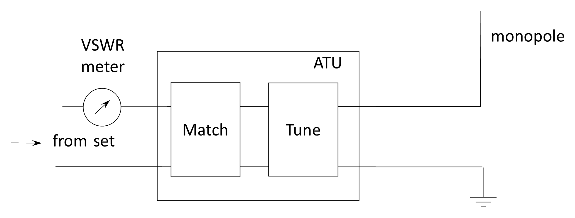
If the radio is to be connected to an antenna whose impedance differs from that of the transmission line, an antenna tuning unit (ATU) is inserted between the set and the antenna to provide impedance transformation. The ATU performs two closely related functions: tuning and matching. In practice these functions are usually achieved simultaneously within a single adjustable network.
- Tuning. If the antenna presents a reactive component (capacitive or inductive), the ATU introduces an equal and opposite reactance so that, at the input terminals of the ATU, the net impedance presented to the transmitter is purely resistive. For example, a short antenna is typically capacitively reactive and requires a series inductance to achieve resonance. Since the electrical length of a fixed physical antenna varies with operating frequency, the reactive component also varies, and the ATU must therefore provide variable inductance and/or capacitance. Adjustment is guided by a reflected-power or VSWR meter, which indicates when the reactive component has been effectively cancelled.
- Matching. Once the reactive component has been neutralized (as seen at the transmitter port), the remaining resistive component may still differ from the characteristic impedance of the transmission line (typically 50 Ω in modern systems). The ATU then transforms this resistance to the required value through an impedance-matching network such as an L-, T-, or π-configuration. The objective is to ensure that the impedance presented to the transmitter equals its design load impedance, thereby minimizing reflected power and maximizing power transfer.
An all-purpose ATU therefore consists of a variable reactive network capable of transforming a wide range of complex antenna impedances into the required load impedance for the transmitter. The device is also referred to as an antenna matching unit (AMU) or simply a coupler. It should be noted that the ATU does not change the intrinsic radiation properties of the antenna; it merely ensures efficient transfer of power between the transmitter and whatever impedance the antenna presents.
Radiation Resistance and Antenna Efficiency
Before leaving the topic of antenna input impedance, it is useful to formalize the concept of radiation resistance. Radiation resistance is defined as the equivalent resistance that accounts for the power radiated by an antenna. It is the value of resistance that, if it were dissipating power as heat, would dissipate the same amount of power as the antenna actually radiates into space.
For a half-wave dipole in free space, the radiation resistance is approximately 72 Ω. This value arises from the current distribution and geometry of the antenna and is independent of conductor losses.
As illustrated in the effective resistance model in Figure 12.7, the total antenna resistance is the sum of its radiation resistance, RR, associated with radiated power and any loss resistance, RL, associated with conductor losses, connection losses, and (for monopoles) ground losses. For a given RMS current I at the feed point, power will be associated with the radiation resistance and dissipated in the loss resistance.
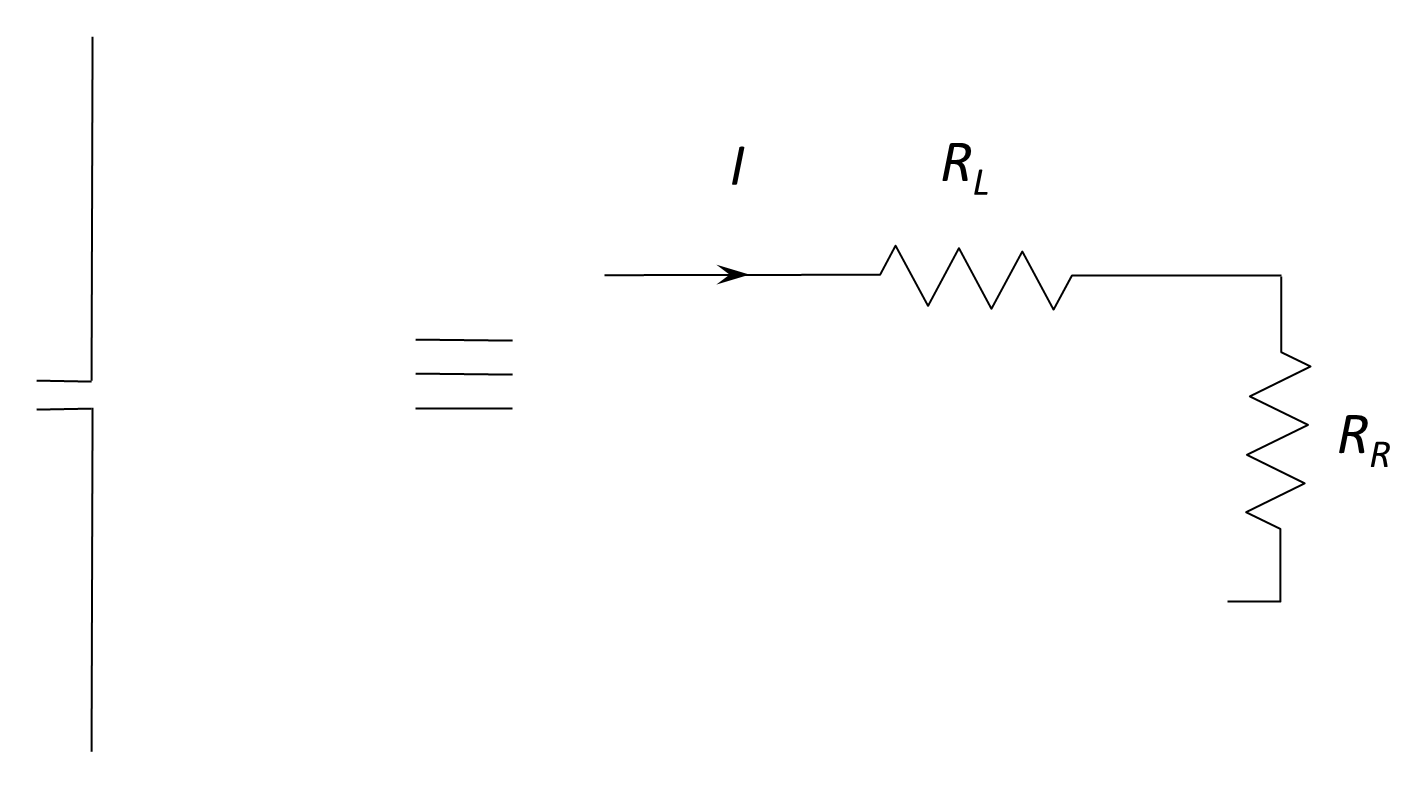
However, since the radiated power will only be from the radiation resistance, RR, with the remaining power dissipated in RL, the antenna’s efficiency is defined as the ratio of radiated power to total input power.
Consequently, antenna efficiency is the ratio of the radiation resistance to the total input resistance:
This expression shows that high antenna efficiency requires the radiation resistance to be large compared with the loss resistance. For full-sized resonant antennas, RR is typically much greater than RL, and efficiency is high. For electrically short antennas, however, radiation resistance becomes small, so even modest loss resistance can significantly reduce efficiency.
Thus, radiation resistance provides a direct link between antenna geometry, current distribution, and radiated power, while antenna efficiency quantifies how effectively the input power is converted into useful radiation rather than dissipated as loss.
Radiation Pattern
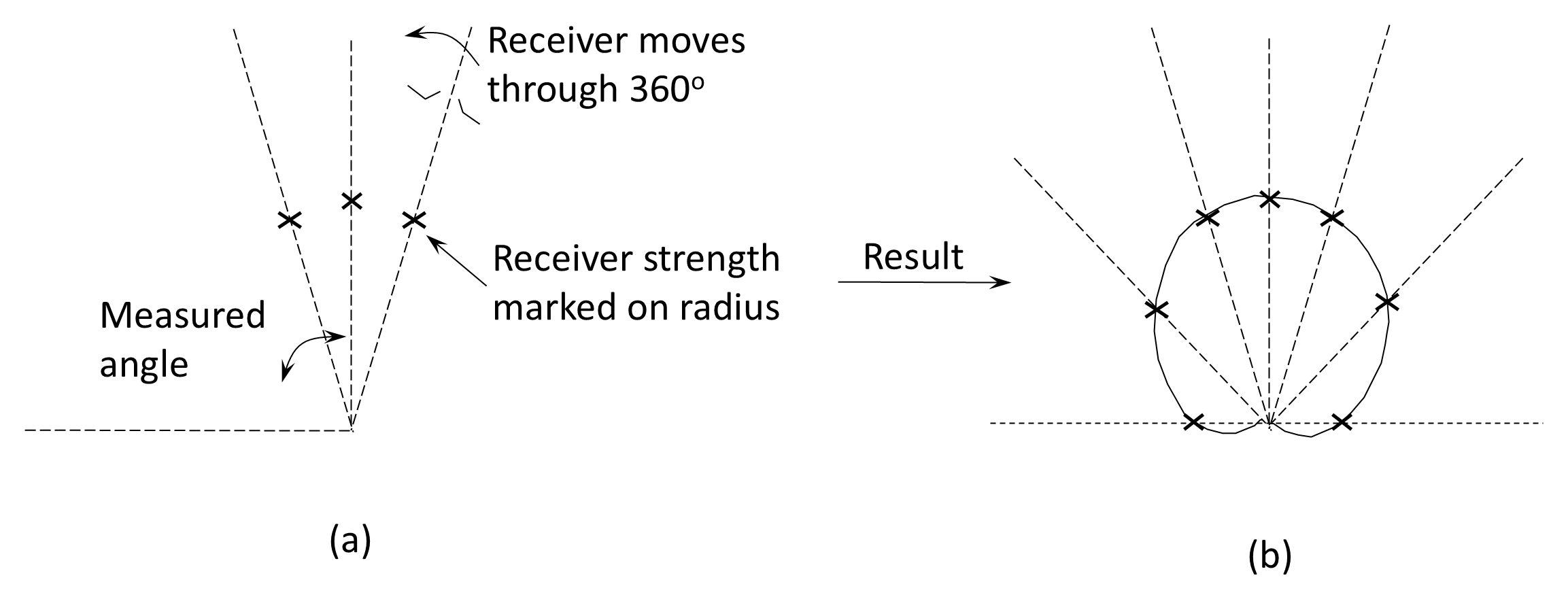
We saw earlier that, in practice, an isotropic radiator is not possible—real antennas have a radiation pattern that must be known so that they can be used effectively. As illustrated in Figure 12.8, this pattern is normally determined by moving around the transmit antenna and measuring the received power at various angles at a constant distance away from the antenna.
Physical Dimensions
Antennas should be small and robust for ease of handling in mobile operations, but they also need to be of a physical size commensurate with their frequency of operation. For long-range (low-frequency), mobile operations, the choice of antenna is problematic and the antennas can sometimes be so large that the mobile unit must stop to erect a suitable antenna. Similarly, if high gain is required (such as in satellite communications where the received signal is very weak), the size of the antenna must be increased and the narrow beamwidth means that the antenna must be carefully aimed at the transmitter, which means that high-gain mobile communication is very difficult.
Back to reading