6.7 PSK
In digital modulation, information is conveyed by selecting one of a finite number of signal states, each corresponding to a distinct point in amplitude–phase space. PSK emerged prominently during early deep-space communication programs and has since become one of the most widely used digital modulation techniques in both civilian and military systems. In PSK, digital information is conveyed by switching the carrier phase among a set of discrete values while maintaining constant amplitude.
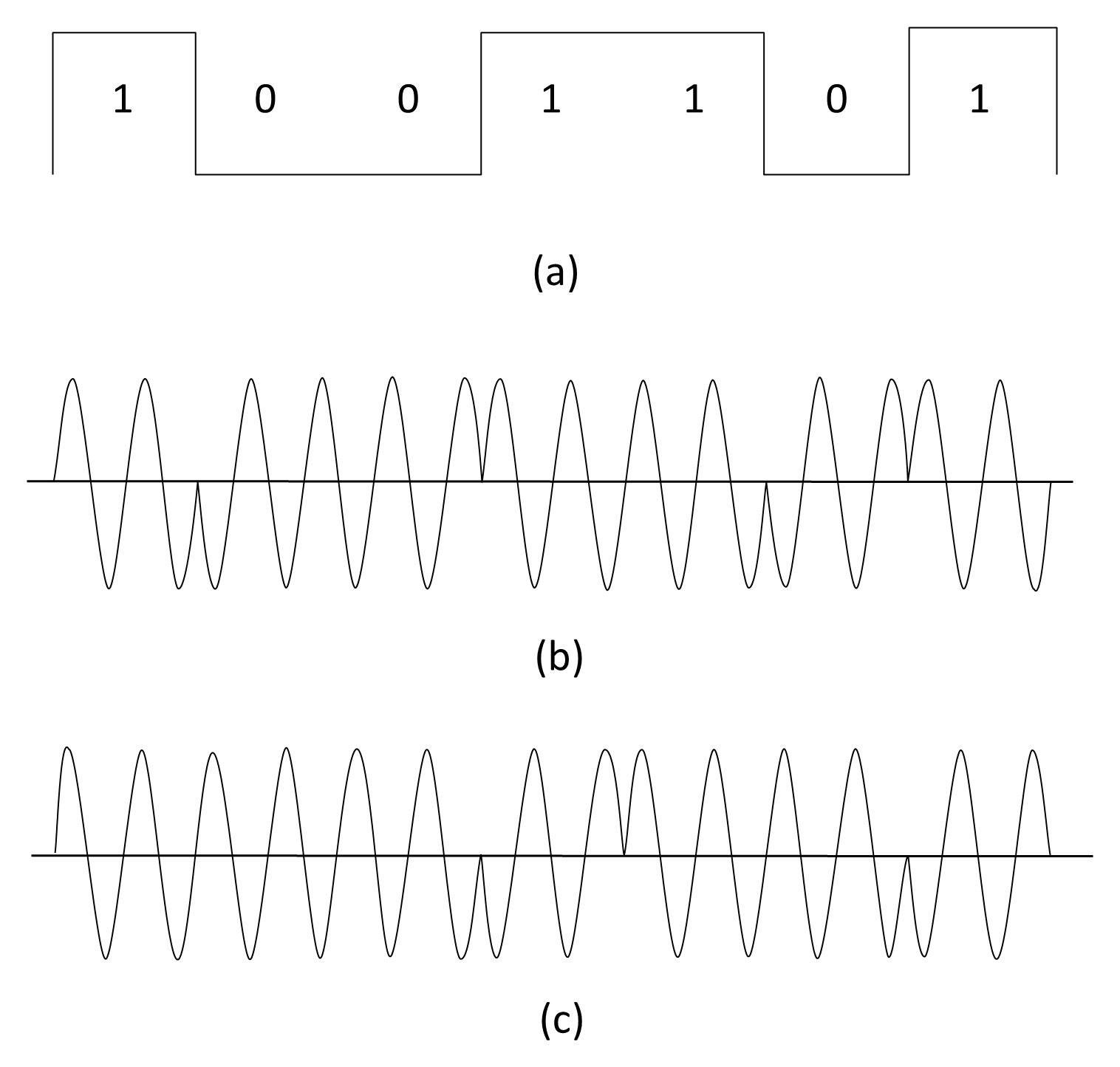
As illustrated in Figure 6.24(b) or a binary data stream, the carrier phase is typically switched between 0° for a logic ‘1’ and 180° for a logic ‘0’, resulting in binary PSK (BPSK). Because only the carrier phase changes, PSK signals are more resistant to amplitude noise and nonlinear distortion than ASK signals.
Figure 6.24(c) also illustrates a variation known as differential phase-shift keying (DPSK) eliminates the need for the receiver to maintain an absolute phase reference using the immediately preceding symbol as the phase reference. In DPSK, information is conveyed in the phase difference between successive symbols. A binary symbol may be represented by either a phase reversal or no phase change, depending on the encoding convention adopted.
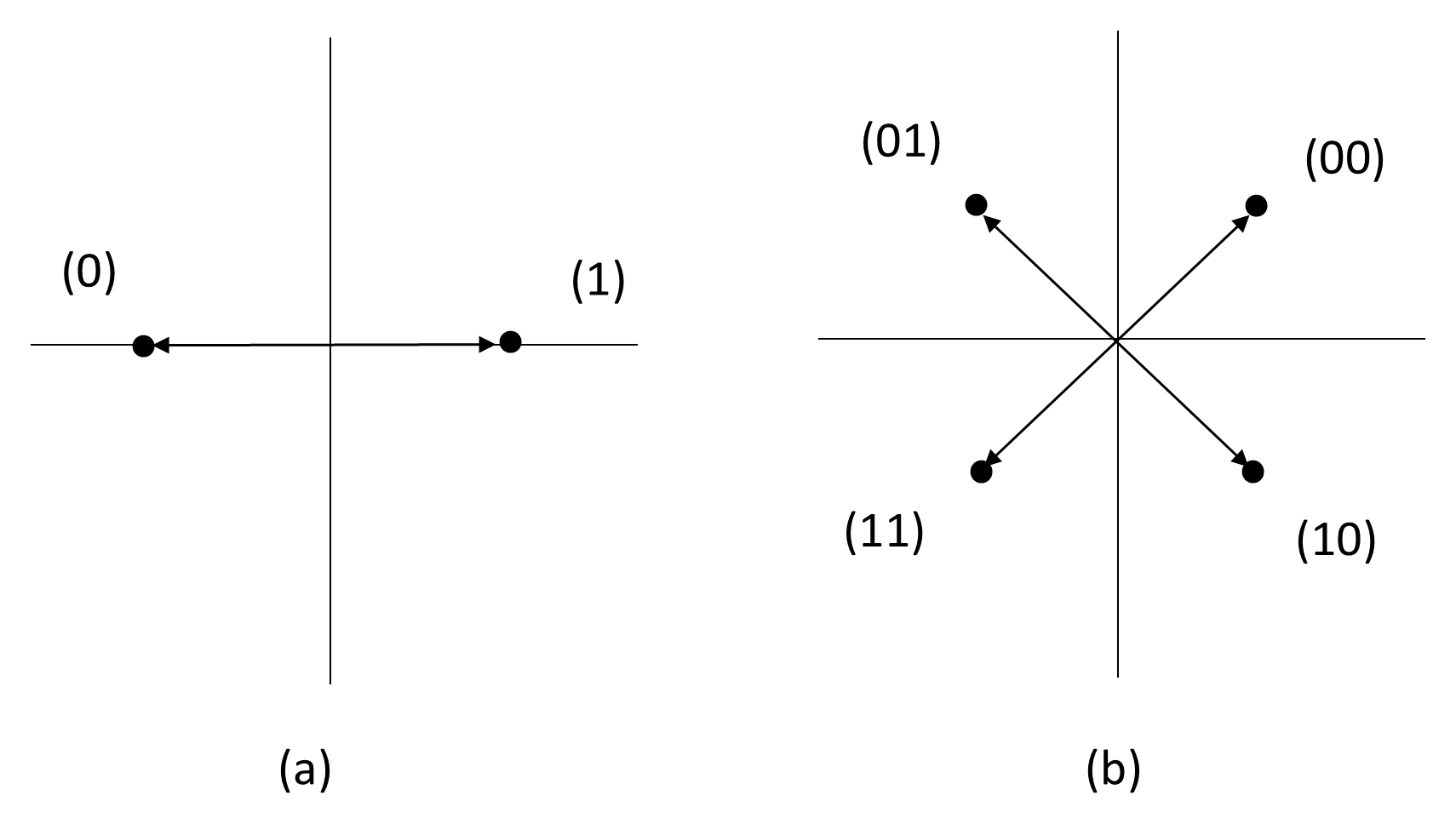
Higher data rates can be achieved while retaining the bandwidth and power efficiency advantages of PSK. For example, the data rate can be doubled using quadrature PSK (QPSK), also known as four-phase PSK or quaternary PSK, in which the carrier takes one of four phase values: 45°, 135°, 225°, and 315°. Each symbol in QPSK represents two bits of information, thereby doubling the bit rate for a given baud rate. Figure 6.25 illustrates the polar (constellation) diagram for BPSK and QPSK systems.
Amplitude and phase modulation can also be combined to produce quadrature amplitude modulation (QAM), in which each symbol is defined by both its amplitude and phase. QAM allows a greater number of symbol states, increasing spectral efficiency at the cost of higher sensitivity to noise and nonlinear distortion.
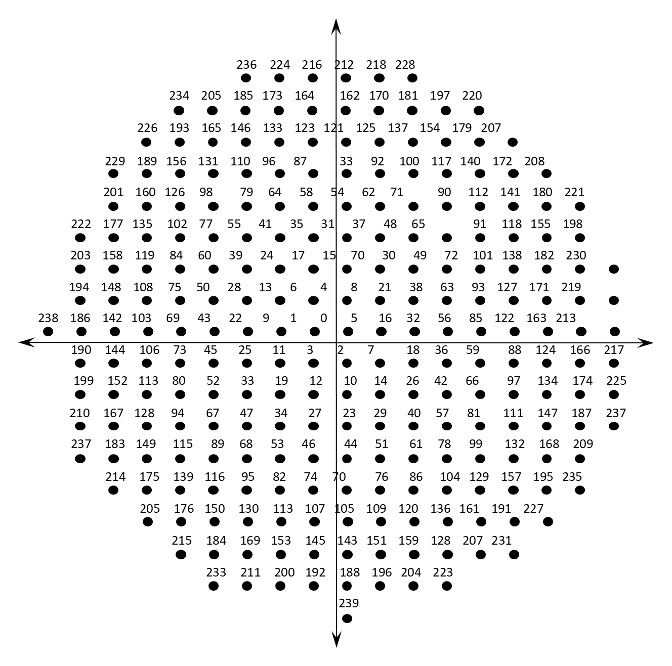
As an example, the V.32 modem standard (9.6 kbps) employed QAM using 45° phase increments and two amplitude levels, yielding 16 distinct states and transmitting 4 bits per symbol. The later V.34 modem employed a larger constellation with 960 signaling points (see Figure 6.26 for 240 signal points—the full constellation is obtained by rotating these points by 0°, 90°, 180° and 270°), operating at 3,200 baud (symbols per second) with 9 bits per symbol, giving a total data rate of 28.8 kbps. Subsequent enhancements to the standard increased the rate to 33.6 kbps. Later modem generations, such as V.90 and V.92, achieved effective downstream rates up to 56 kbps by exploiting digital compression and the digital connection between the service provider and the telephone network, rather than by further expanding the QAM constellation.
The same principles of QAM and PSK form the basis of modern digital communication systems. These techniques are now used extensively in satellite, microwave, and broadband terrestrial links, where higher-order constellations (such as 8PSK, 16QAM, and 64QAM) are employed to achieve higher data throughput while maintaining efficient use of bandwidth and power.