
6.7.5 Error Rate
When a BPSK or QPSK signal is received, it will have accumulated additive white Gaussian noise (AWGN) in the channel. The receiver is therefore assumed to operate over an AWGN channel.
6.7.5.1 BPSK
Since AWGN is additive and Gaussian, the BPSK receiver must decide between two voltage levels whose probability distributions are shown in Figure 6.32.
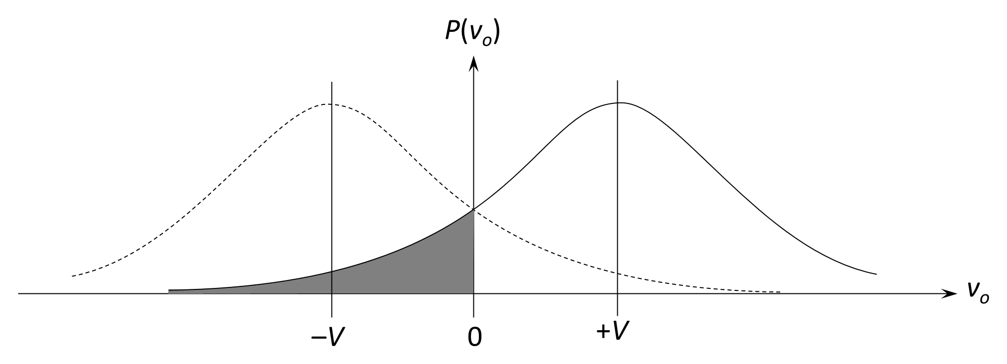
The transmitter sends a carrier that is modulated by the message m(t), which takes the values +1 and −1 to represent logical ‘1’ and ‘0’, respectively. At the receiver, the demodulator output vo is the sum of the signal sample ±V and the Gaussian noise, n(t):
The receiver decides in favor of a ‘1’ if the detected voltage exceeds 0 V, and in favor of a ‘0’ if it is less than 0 V. The probability of error, Pe, is the probability that a ‘1’ was transmitted and a voltage less than 0V is received (that is the noise is less than –V) or that a ‘0’ is transmitted and a voltage greater than 0 V is received (that is the noise is greater than +V).
To ensure that the symbols are sent equally often, the transmitter includes a scrambler or randomizer, that prevents long sequences of identical bits. Scrambling also provides energy dispersion to reduce mutual interference between systems. A randomized bit stream spreads the carrier energy across the spectrum, avoiding discrete spectral lines that can arise from repetitive sequences. The scrambling process is analogous to stream encryption, using a pseudo-random sequence generator and modulo-2 addition.
The probability that the noise exceeds +V is represented by the shaded areas under the Gaussian tails in Figure 6.32 and is given by:
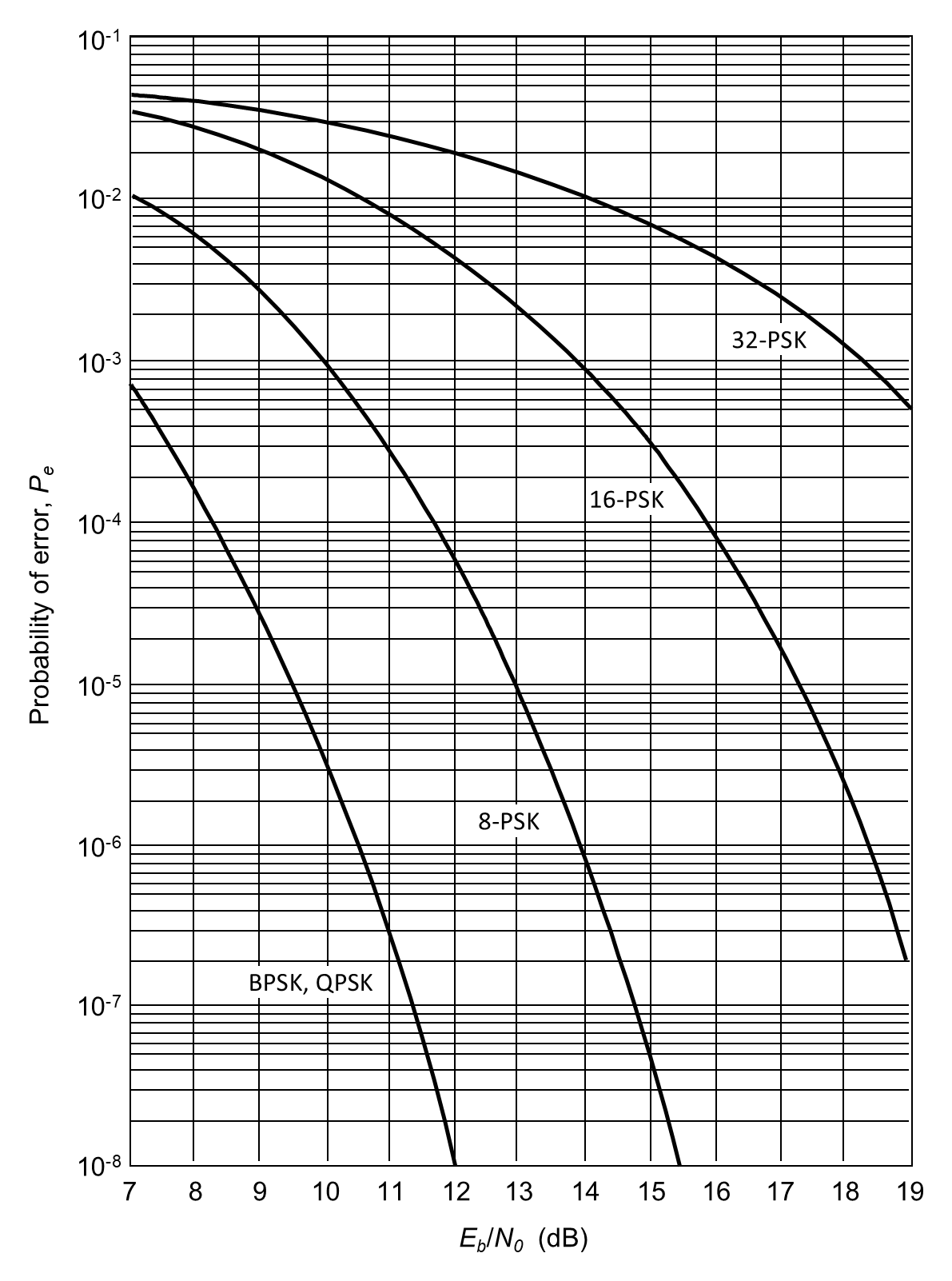
where erfc(x) is the complementary error function, which is tabulated in many reference books. Figure 6.33 plots the probability of error versus Eb/N0 for several digital modulation schemes. Note that Eb/N0 ratio in Equation (6.51) is a linear ratio, not a decibel value, and must be converted from dB before substitution.
We can also consider the probability of error in terms of the C/N ratio. We saw earlier that:
For a BPSK receiver with ideal RRC filters, the noise bandwidth is approximately equal to the symbol rate multiplied by (1 + α), where α is the roll-off factor. For small roll-off factors, B ≈ Rb, and thus C/N ≈ Eb/N0. Since Es=Eb for BPSK:
Therefore, the probability of error for BPSK may be expressed either in terms of Eb/N0 or C/N:
As before the C/N ratio must be expressed as a normal (linear) ratio, not in decibels, before use.
In practical systems, deviations from the ideal model arise due to non-ideal filters, imperfect carrier recovery, and other implementation losses. These are accounted for through an implementation margin in C/N. Typical margins range from 0.5 dB for low-bit-rate systems to 2 dB for high-bit-rate systems.
6.7.5.2 QPSK
Since QPSK conveys two bits per symbol, the symbol energy is Es=2Eb. For equal Eb/N0, BPSK and QPSK exhibit identical bit-error performance. For equal carrier-to-noise ratio C/N, QPSK transmits twice as many bits per symbol as BPSK while maintaining the same error probability:
Thus, while BPSK and QPSK occupy the same bandwidth and yield the same probability of error for a given Eb/N0 ratio, for equal carrier-to-noise ratio (C/N), QPSK achieves the same bit-error performance as BPSK while transmitting twice as many bits per symbol. Equivalently, for a fixed bit rate and bandwidth, BPSK and QPSK require the same Eb/N0 to achieve identical error probability.
6.7.5.3 MPSK
For higher-order M-ary PSK systems (M ≥ 4), each symbol represents nb =log2 M bits and the approximation to the symbol error probability for coherent MPSK in AWGN is:
where Es is the symbol energy, N0/2 is the noise power spectral density and is the Gaussian Q-function. This expression is accurate at moderate-to-high signal-to-noise ratios.
For Gray-coded constellations, the bit error rate (BER) may be approximated as Pb = Ps / nb since most symbol errors correspond to a single bit error.
6.7.5.4 Acceptable BER
Acceptable BERs vary widely depending on the application and the nature of the information being transmitted. For voice communications, a BER on the order of 10–3 may be acceptable, whereas data and digital video applications typically require BERs as low as 10–9 to 10–11.
Many commercial satellite providers normally guarantee links of the required capacity with a minimum bit-error rate, typically 10–6, for a defined percentage of time. This performance is achieved by incorporating a link margin sufficient to accommodate major propagation impairments such as rain attenuation, scintillation, and thermal noise. If a lower BER is required, channel coding must be applied to introduce redundancy that allows detection and correction of bit errors. Coding schemes of this type are discussed in detail in Chapter 4.
In more controlled environments, such as military satellite communication networks and some private commercial systems, protocols and channel coding are integral components of the overall network architecture and are implemented directly by the network operator to meet stringent reliability requirements.
Required Eb/N0 and link margin are therefore determined by the target BER after coding, the chosen modulation scheme, and the statistical availability requirement of the link.
Back to reading