
6.7.1 BPSK
In BPSK the baseband signal m(t) is used to phase-modulate the carrier:
As m(t) varies between +1 and –1, the RF carrier undergoes phase shifts of 0 and π corresponding to the two binary states. Using the relationship:
Equation (6.41) can be re-written as:
which greatly simplifies the implementation of a BPSK modulator, since it can be realized by carrier multiplication with the bipolar data stream.
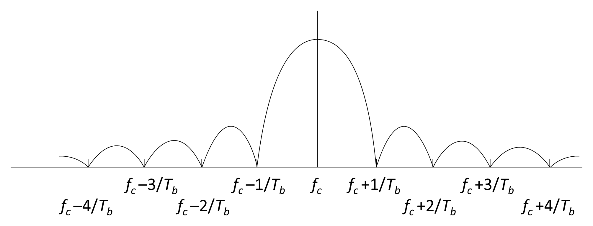
Figure 6.27 illustrates the spectrum of a BPSK waveform generated using a polar NRZ baseband signal, with power spectral density given by:
Note that, for a rectangular NRZ pulse shape, the BPSK waveform has a bandwidth requirement of B = 2/Tb, indicating that the signal occupies twice the bit rate in hertz. In practice, pulse-shaping filters such as root-raised cosine (RRC) filters are employed to control spectral occupancy and reduce adjacent-channel interference.
6.7.1.1 QPSK
In QPSK the baseband signal m(t) is divided into two separate streams, which are used to phase-modulate two carrier waves in quadrature—that is, 90° out of phase with each other. As illustrated in Figure 6.28(a), this implementation produces a modulated carrier of the form:
which can be re-arranged as:
This shows that a QPSK signal can also be generated by phase-shifting a single carrier in accordance with the ratio of the two message components, as depicted in Figure 6.28(b).
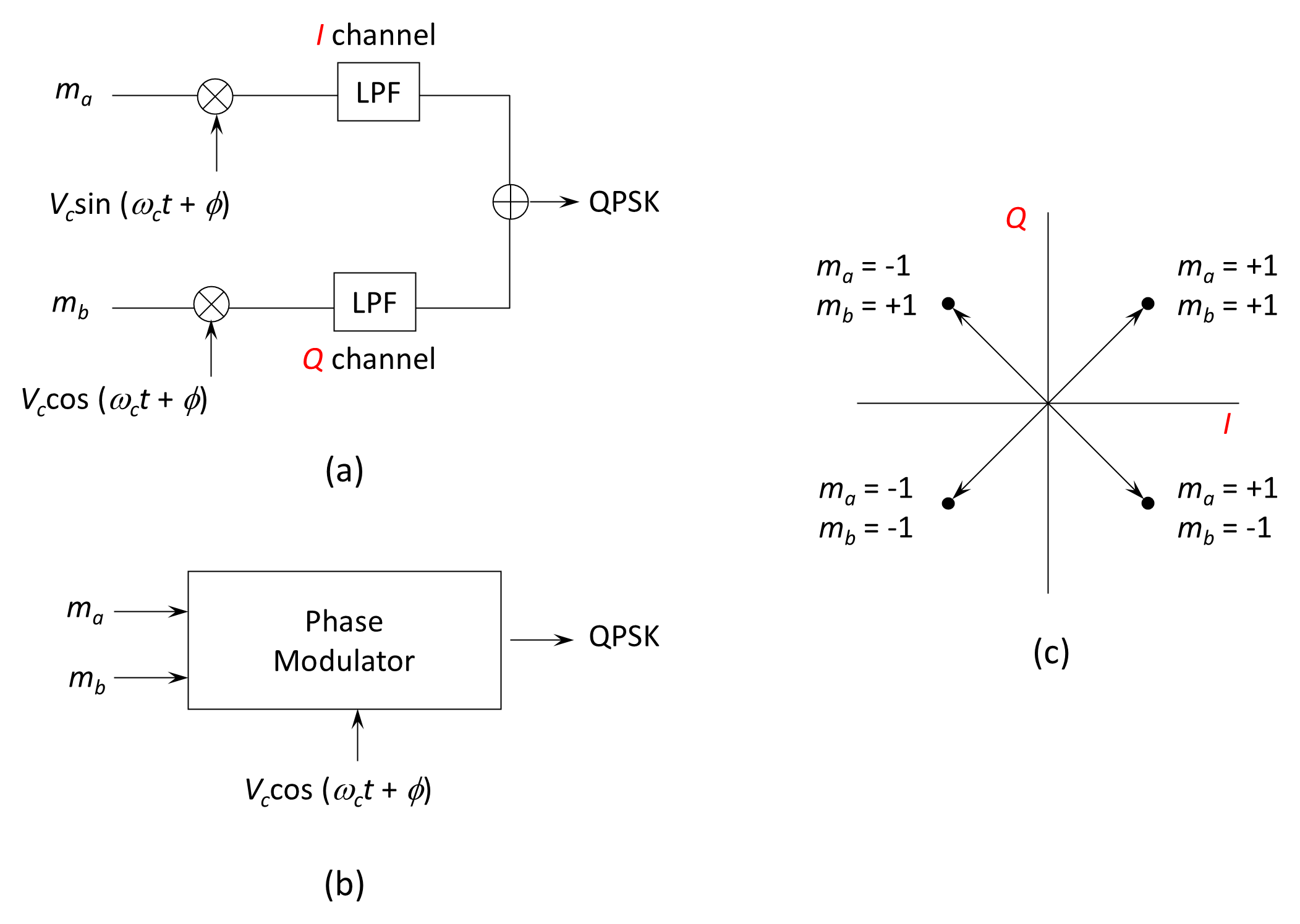
The spectrum of a QPSK waveform is the sum of the individual spectra of its two quadrature baseband components. If the message streams are identical in waveform and bit period, the resulting QPSK spectrum is effectively the same as that of BPSK. Thus, QPSK achieves twice the data rate of BPSK without increasing the occupied bandwidth, a key advantage in bandwidth-constrained systems such as satellite links.
Several variations of QPSK have been developed to improve performance or reduce phase transitions:
- Offset QPSK (OQPSK). The two baseband bit streams are offset by one-half of the bit period, limiting the maximum instantaneous phase shift of the carrier to 90°. OQPSK retains the same spectral shape as conventional QPSK but reduces the likelihood of signal envelope variations.
- Minimum-Shift Keying (MSK). A continuous-phase modulation derived from OQPSK in which the offset NRZ data are replaced with half-period sinusoidal waveforms. MSK provides smoother phase transitions and results in a main spectral lobe slightly broader than QPSK, but with much smaller spectral sidelobes.
Although OQPSK and MSK offer certain implementation advantages, they are not widely used in satellite communications, where conventional QPSK remains the preferred standard due to its simplicity and efficiency.
The carrier-to-noise ratio (C/N) for the modulated signal is expressed as:
where N0 is the noise power spectral density and B is the bandwidth over which the ratio is measured.
The carrier power, C, can also be expressed in terms of the energy per symbol, Es, and the duration of the symbol period, Ts (or equivalently, the symbol rate Rs):
so that the C/N ratio can be expressed in terms of the Es/N0 ratio:
For BPSK, each symbol represents a single bit, so Es=Eb. In practice the Eb/N0 ratio cannot be measured directly, system performance is typically characterized in terms of C/N, which can be converted to Eb/N0 using the above relationship.
Back to reading