6.3 AMPLITUDE MODULATION
As its name implies, amplitude modulation (AM) uses the characteristics of the modulating signal to vary the amplitude of a carrier frequency. The simplest case of this is where the amplitude of the carrier signal is switched on and off in accordance with some agreed sequence such as the Morse code. Any complex analog signal, however, can be used to modulate the carrier. Fortunately, as we saw in Chapter 2, any complex signal can be considered as a sum of simple sine waves. Our analysis task is therefore much easier since we can study modulation by a single tone and infer from that knowledge the modulation of a carrier by a more complex waveform. Using the sinusoidal carrier of Equation (6.1), and ignoring the phase:
The mechanism of AM can perhaps best be understood in the simple case where the modulating signal is also sinusoidal and is given by:
The amplitude of the carrier is caused to vary sinusoidally (with an angular frequency of ωm, or a frequency of fm) about a mean value of Vc volts with a maximum variation of ±Vm volts. The instantaneous voltage of the AM wave is then:
Figure 6-1 shows a sinusoidally modulated wave where a 1-kHz sine wave has amplitude modulated a 10-kHz carrier. Before we consider some of the characteristics of the AM waveform, let’s see how Equation (6.5) relates to Figure 6.1. First note that we have not affected the frequency of the carrier, which remains constant. What we have affected is the amplitude. We did this by varying it around a resting amplitude Vc, which is the unmodulated carrier amplitude. If we look at the positive side of the waveform, Figure 6.1 shows that when the modulating waveform is at its maximum (+Vm), the modulated carrier has a maximum amplitude of (Vc+Vm). When the modulation is at its minimum (−Vm), the modulated carrier has a minimum amplitude of (Vc−Vm). When the modulating waveform has zero amplitude, the carrier is unmodified and has its original amplitude, Vc. We can see a similar effect on the negative (lower) half of the waveform. Therefore, as you can see in Figure 6-1(b), the effect of the amplitude modulation is to impress the shape of the modulating waveform onto the amplitude of the carrier.
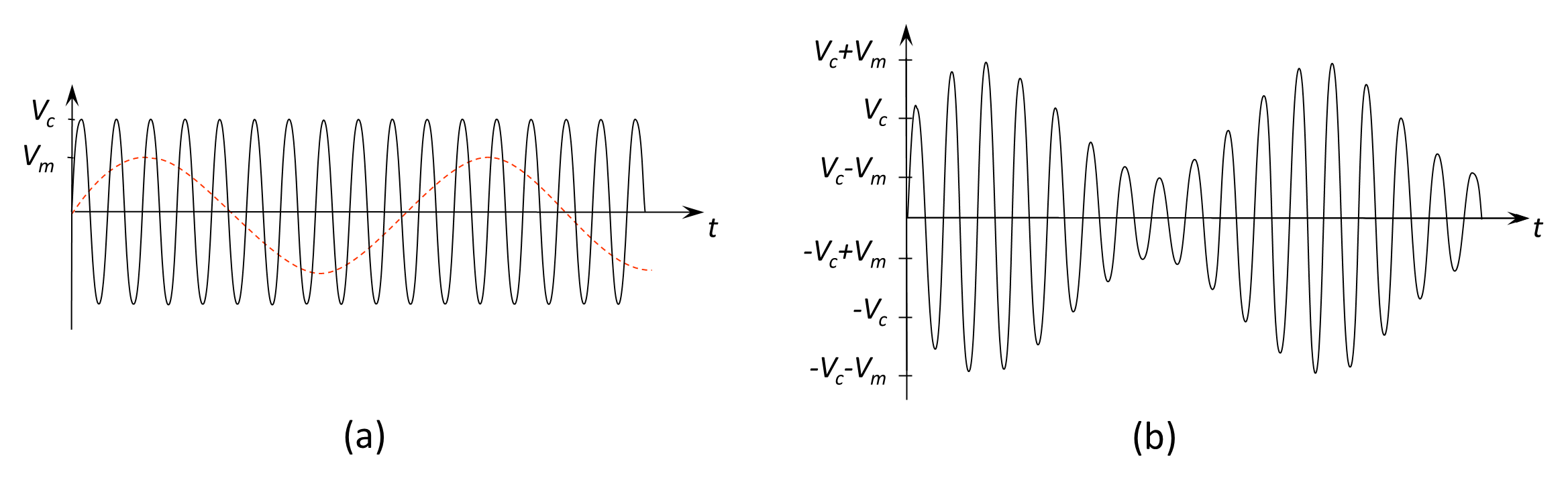
The outline of an AM wave is known as the modulation envelope. As shown in Figure 6-1, the modulation envelope, on both the positive and negative side of the waveform, resembles the outline shape of the modulating signal. The envelope varies between |Vc+Vm| and |Vc−Vm|.
Expanding, Equation (6.5) becomes:
and using the trigonometric relationship:
Equation (6.6) becomes:
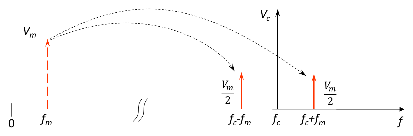
This expansion is useful because Equation (6.8) shows that a sinusoidally modulated carrier wave contains components at three different frequencies: the original carrier frequency (fc); a lower sidefrequency (fc–fm); and an upper sidefrequency (fc+fm). (It is important to note that original baseband frequency does not appear directly in the spectrum; it is translated to sidebands around the carrier.)
The form of amplitude modulation expanded in Equation (6.8), in which the carrier remains present and both upper and lower sidebands are transmitted, is known as conventional AM. It is also referred to as double-sideband with large carrier (DSB-LC) or double-sideband full carrier (DSB-FC) modulation.
Conventional AM is straightforward to generate and, importantly, can be demodulated using a simple envelope detector. However, because the carrier conveys no information and both sidebands contain identical information, it is inefficient in both power and bandwidth. These inefficiencies motivate the development of suppressed-carrier and single-sideband techniques discussed in the following Sections 6.2.1.6 and 6.2.1.7. Beforehand, however, we complete our investigation of conventional AM.
Figure 6.2 shows the frequency domain representation of a carrier frequency fc modulated by a single sine wave of frequency fm. The original frequency fm (dotted line) is translated by the modulation process to become two sidefrequencies around the carrier, each of which is half the size of the original.
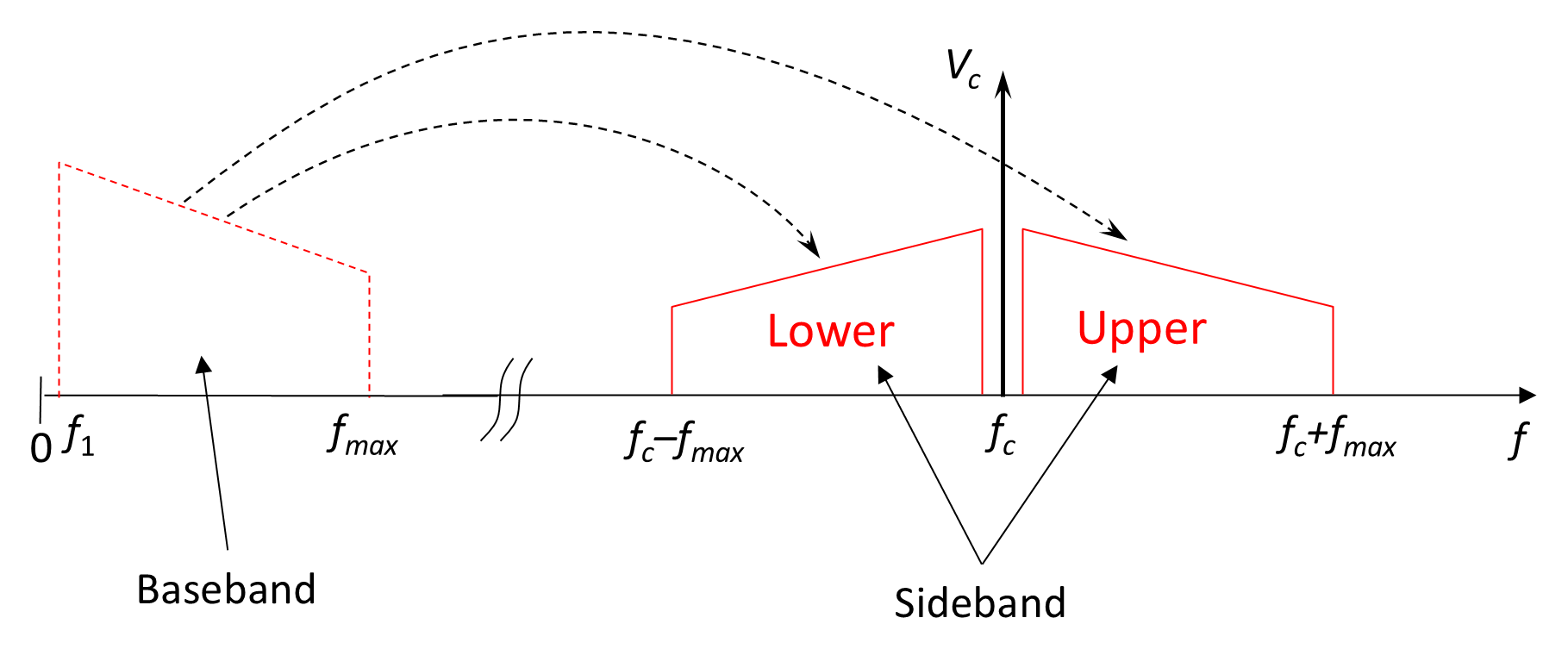
As we noted earlier, although the modulating signal waveform is rarely purely sinusoidal, it can be viewed as the sum of a number of sinusoids; in which case each component frequency of the modulating signal produces corresponding upper and lower sidefrequencies in the modulated wave, and the modulation envelope will have the same shape as the modulating waveform. The result is, instead of a single sidefrequency above and below the carrier, two bands of frequencies (in sidefrequency pairs) are produced, one above and one below the carrier. The band of sidefrequencies below the carrier is called the lower sideband and the band above is called the upper sideband. The frequency domain representation of sidebands is shown in Figure 6.3. Note that the sidebands for AM are normally drawn with a shaped amplitude. This does not in any way indicate the relative amplitudes of the various frequency components within the sideband but simply serves to show the location of the carrier.