
14.3.4 Physical Layer Evolution
Although the Ethernet frame structure has remained fundamentally unchanged since the original 10 Mbps specification, the physical-layer signaling techniques used to convey those bits have evolved dramatically to support higher data rates over copper and optical media. In IEEE 802.3 terminology, the physical layer (PHY) defines the signaling method, line coding, and electrical or optical interface characteristics.
Early Ethernet employed uniform signaling across media types, and maximum segment length was determined primarily by attenuation in the transmission medium. The naming convention reflected this structure using the format <speed (in Mbps)>-<transmission type>-<segment length (in hundreds of meters)>. Thus, 10BASE-5 denoted thick coaxial cable (500 m segments), 10BASE-2 thin coaxial cable (200 m), 10BASE-T twisted pair (100 m), and 10BASE-F fiber-optic links (up to approximately 2 km, depending on variant).
For copper Ethernet, the standardized interface uses four balanced twisted pairs terminated in an 8P8C modular connector (commonly referred to as RJ-45). While signaling techniques have advanced substantially, this four-pair interface has remained consistent across generations. Increasing data rates have been achieved through progressively more sophisticated encoding, modulation, and digital signal processing over the same basic cabling infrastructure, supporting long-term backward compatibility.
The original 10BASE-T Ethernet employed Manchester encoding (see Appendix D), in which each bit period contained a transition to provide clock recovery. While robust and self-clocking, Manchester encoding requires a signaling rate twice the data rate, limiting spectral efficiency.
Fast Ethernet (100BASE-TX) introduced more efficient line coding, including 4B/5B block encoding combined with MLT-3 signaling (see Appendix D), increasing throughput while controlling bandwidth.
Gigabit Ethernet over copper (1000BASE-T) adopted PAM with five levels (PAM-5) and transmitted simultaneously over all four twisted pairs using sophisticated echo cancellation and crosstalk mitigation. PAM-5 encodes multiple bits per symbol by using discrete voltage levels rather than binary transitions.
At 10 Gbps and beyond, copper standards such as 10GBASE-T and later multi-gigabit variants employ higher-order pulse amplitude modulation (e.g., PAM-16) combined with FEC, digital signal processing, and advanced equalization to maintain signal integrity over short distances.
Modern high-speed optical Ethernet standards (e.g., 100G, 400G, 800G) use multi-lane serial transmission and, in many cases, PAM-4 (four-level pulse amplitude modulation) to double the number of bits transmitted per symbol relative to traditional NRZ signaling.
As data rates increased, the shared-medium constraints that governed early Ethernet became less sustainable. In CSMA/CD networks, maximum cable length and repeater counts were tightly specified to ensure collision detection within one slot time (512 bit-times). To extend network reach beyond a single cable segment, repeaters were introduced to regenerate signals and connect multiple segments into a larger logical bus. However, all repeater-connected segments remained part of the same collision domain and were therefore still subject to strict timing and diameter limits (such as the well-known “5-4-3 rule” in early Ethernet designs).
As the number of users increased, contention within large collision domains reduced efficiency. To improve scalability, bridges were introduced to segment the network into multiple collision domains while forwarding frames selectively based on MAC addresses. Bridges reduced unnecessary traffic propagation and improved aggregate throughput, but they introduced additional complexity in topology management and spanning-tree control.
The decisive architectural shift occurred with the widespread adoption of Ethernet switches, which evolved from multi-port bridges. In switched Ethernet, each device connects to a dedicated switch port, creating point-to-point links rather than a shared bus. Full-duplex operation eliminates collisions entirely and disables CSMA/CD. Segment length is therefore determined primarily by attenuation and PHY design rather than propagation-delay constraints, and the number of connected users is governed by switch capacity and network architecture rather than by collision-domain limitations. Figure 14.6 provides a brief comparison of shared-medium Ethernet and modern switched Ethernet.
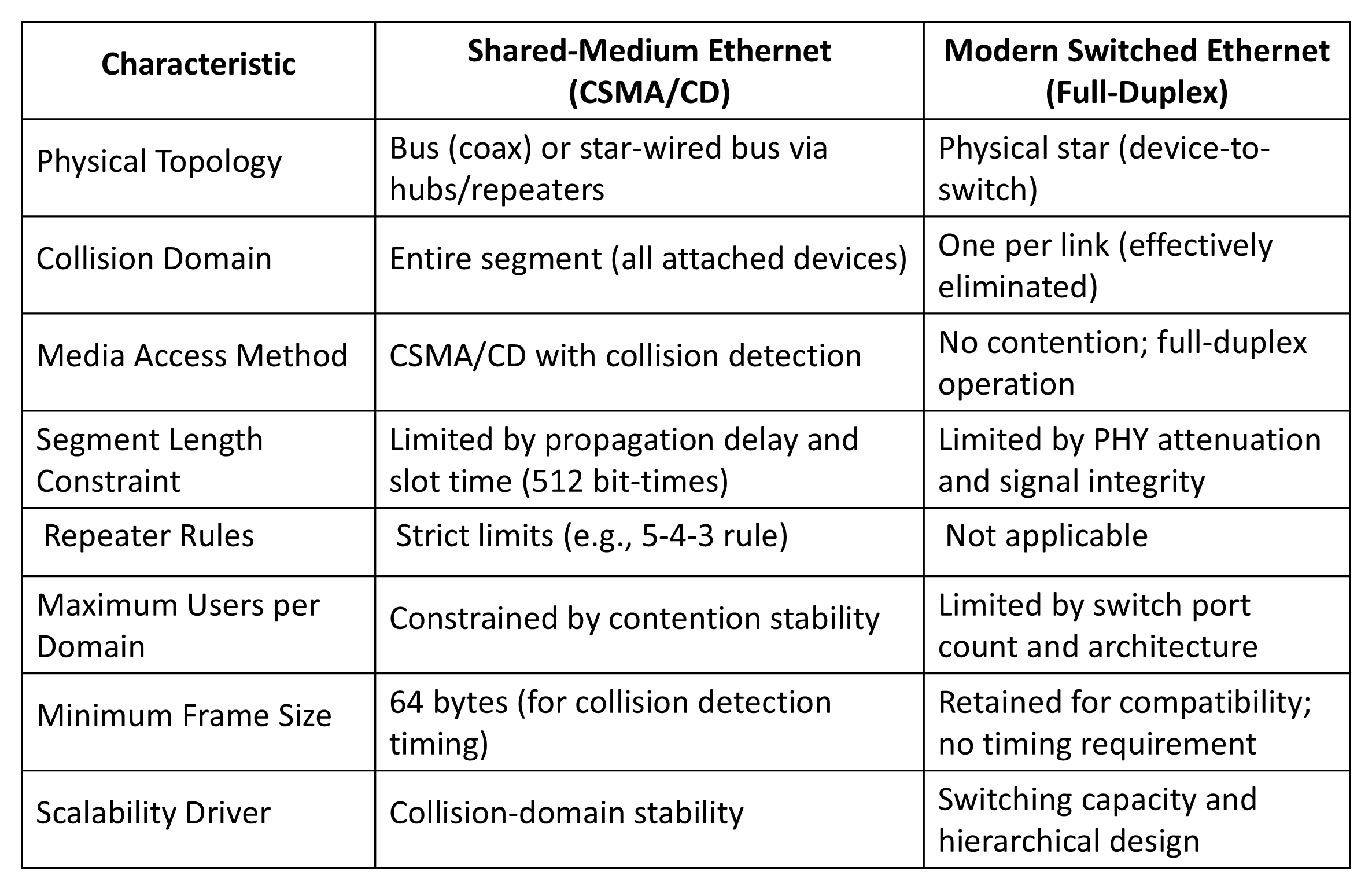
Thus, while Ethernet’s logical frame format has remained stable, the underlying PHY implementations and network architectures have evolved from shared coaxial buses with repeaters to switched, full-duplex systems employing sophisticated multi-level, multi-lane modulation supported by advanced digital processing.
These PHY techniques are realized over specific transmission media, whose electrical and optical properties ultimately determine achievable distance, bandwidth, and deployment characteristics.
Back to reading