
10.3.2 Optical Fibers
As illustrated in Figure 10.18, an optical fiber consists of a thin glass core surrounded by a glass cladding and a protective jacket. Electrical signals modulate a laser or light-emitting diode (LED), converting electrical pulses into light pulses that travel along the fiber. Propagation is confined to the core because its refractive index is slightly higher than that of the cladding, causing total internal reflection at the core–cladding boundary. At the receiving end, the light pulses are detected by photodiodes and reconverted into electrical signals.
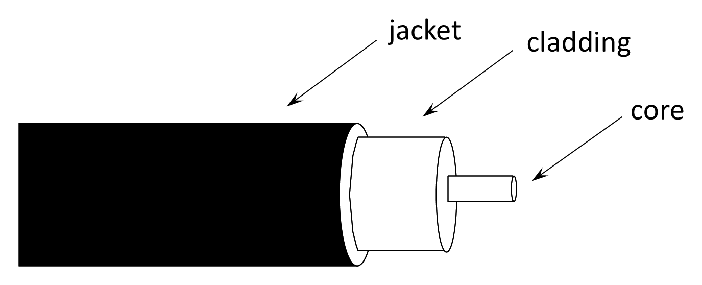
In contrast to metallic waveguides, optical fibers guide energy within a dielectric medium. The electromagnetic wave propagates primarily within the core, with an evanescent field extending slightly into the cladding. The confinement mechanism is total internal reflection rather than metallic boundary reflection.
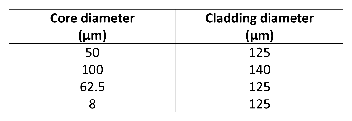
Standard core and cladding diameters are summarized in Figure 10.19, with 50/125 µm, 62.5/125 µm, and 8/125 µm being the most common commercial sizes.
10.3.2.1 Types Of Optical Fiber
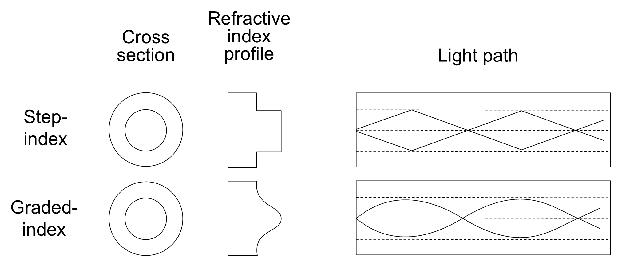
As shown in Figure 10.20, there are two principal types of multimode fiber:
- Step-index fiber. The refractive index of the core is uniform and abruptly decreases at the cladding boundary. Light rays reflect sharply at this interface, forming multiple discrete propagation paths or modes.
- Graded-index fiber. The refractive index of the core gradually decreases from the center toward the edge. Rays bend smoothly rather than reflecting sharply, which reduces modal dispersion because the longer optical paths near the outer edge correspond to higher propagation velocities.
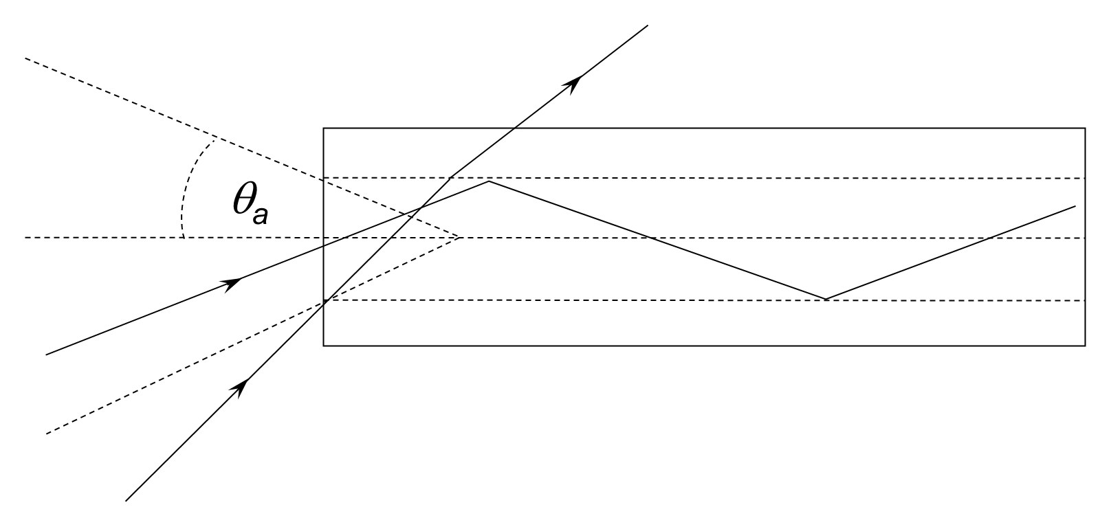
The numerical aperture (NA) of an optical fiber defines the acceptance cone within which light is guided. Figure 10.21 illustrates the acceptance angle. Light entering the fiber at an angle less than the acceptance angle is totally internally reflected, while light entering at larger angles escapes through the cladding. The numerical aperture determines the fiber’s coupling efficiency with the light source and is defined from Snell’s law at the fiber entrance:
where n1 is the refractive index of the core, n2 that of the cladding, n0 the refractive index of the external medium (≈1 for air), and θₐ the acceptance half-angle.
10.3.2.2 Single-Mode And Multimode Fibers
As light propagates along the core, multiple reflection paths lead to interference between modes. Both step-index and graded-index fibers are multimode and allow several modes to exist simultaneously, resulting in modal dispersion—different modes arrive at the receiver at slightly different times.
In addition to modal dispersion, optical fibers exhibit chromatic dispersion, arising from wavelength-dependent propagation velocity, and polarization-mode dispersion in single-mode fibers. Modern long-haul systems employ dispersion-compensating techniques and wavelength-division multiplexing (WDM)—see Section 7.3—to maximize capacity.
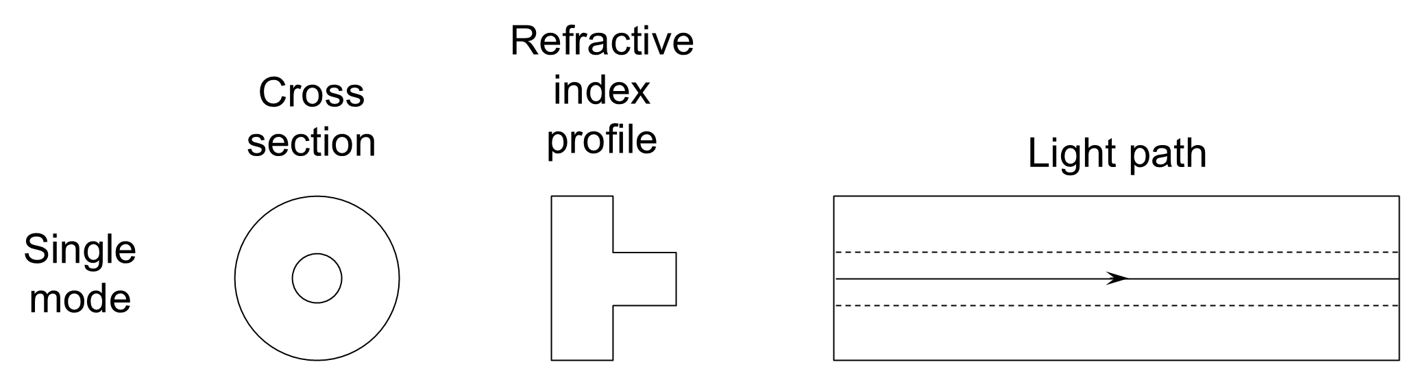
Single-mode fibers restrict propagation to only one mode by using a very small core, typically 8 µm in diameter, as shown in Figure 10.22. Only rays that strike the wall of the core at near-grazing incidence are supported. Because dispersion is minimized, single-mode fibers allow much greater transmission distances and higher bandwidths. However, their small acceptance angle makes splicing and termination more difficult and limits the allowable bend radius.
Typical dimensions are:
- Multimode fiber: 50 µm or 62.5 µm core, 125 µm cladding (50/125 µm or 62.5/125 µm).
- Single-mode fiber: approximately 9 µm core with 125 µm cladding (9/125 µm).
10.3.2.3 Losses In Optical Fibers
Optical fibers exhibit much lower attenuation than metallic cables, Contemporary low-loss single-mode fibers achieve attenuation below 0.18 dB km⁻¹ at 1.55 µm. The significantly lower losses allow repeater spacing of 20–30 km, and up to 300 km with optical amplification. The principal losses arise from absorption and Rayleigh scattering within the glass, primarily due to residual impurities and molecular irregularities. Attenuation is strongly wavelength-dependent: minima occur near 1.3 µm and 1.55 µm, where modern systems typically operate. Modern single-mode fibers operating near 1.55 µm achieve attenuation as low as 0.17–0.20 dB/km, primarily limited by Rayleigh scattering and intrinsic material absorption. Additional losses arise from bending, splicing, connector misalignment, and microbending effects.
10.3.2.4 Polymer Optical Fibers
Polymer optical fiber (POF) provides a practical and economical alternative to glass fiber in short-range applications. In general, POF is less expensive and more mechanically resilient than silica-based fibers, tolerating bend radii of less than 20 mm without significant performance degradation. It operates reliably across a wide temperature range (typically −40 °C to +85 °C), does not oxidize, and performs well in humid or salt-laden environments. These characteristics make it particularly suitable for industrial, automotive, marine, and consumer installations where environmental robustness is important.
In addition to its environmental durability, POF is easy to handle and terminate, requiring less specialized tooling and skill than glass fiber systems. Its relatively large core diameter simplifies connectorization and alignment, making it tolerant of minor misalignment and reducing installation time and cost. The large diameter also facilitates coupling from low-cost light sources such as LEDs. Although POF exhibits higher attenuation than silica fiber and is therefore generally limited to shorter transmission distances, its durability, flexibility, and low installation complexity make it an attractive solution for cost-sensitive and mechanically demanding applications.
10.3.2.5 Advantages And Disadvantages Of Optical Fibers
Transmission through glass or polymer optical fibers offers significant performance advantages over conventional metallic conductors in both telecommunications and data networking applications. Fiber technology overcomes many of the intrinsic electrical limitations of copper-based media and has become the dominant guided-wave transmission medium for high-capacity systems.
The principal advantages of optical fiber transmission are as follows:
- Higher data rates. Optical carriers operate at frequencies that are many orders of magnitude higher than those used in electrical transmission. Consequently, optical fibers provide extremely large usable bandwidths and support very high data rates. Unlike metallic cables, whose resistance, inductance, and capacitance impose low-pass filtering effects that limit achievable bit rate and distance, fiber systems routinely support multi-gigabit and terabit transmission over long spans. Dense wavelength-division multiplexing (DWDM) further multiplies capacity by allowing numerous wavelength channels to coexist within a single fiber.
- Immunity to crosstalk. Because optical fibers are dielectric waveguides rather than electrical conductors, they do not generate external magnetic fields and are not susceptible to electromagnetic coupling from adjacent cables. As a result, there is no inter-channel crosstalk of the type encountered in multi-pair copper cables.
- Immunity to electromagnetic interference (EMI). Optical fibers neither conduct nor radiate electrical energy. They are therefore unaffected by lightning, switching transients, electric motors, industrial equipment, and other sources of electromagnetic noise. This property makes fiber especially suitable for electrically noisy environments and for installations near high-voltage equipment.
- Environmental resilience and durability. Glass and polymer fibers are resistant to corrosion and are largely unaffected by moisture and most chemical agents which contributes to improved operational reliability compared with metallic facilities. Consequently, fiber cables can operate over wide temperature ranges and are less vulnerable than metallic cables to environmental degradation, particularly in harsh industrial or marine environments. With appropriate mechanical protection, optical fiber systems provide long service life and stable performance.
- Safety and installation advantages. Since fibers carry optical power rather than electrical current, there is no risk of spark generation, ground loops, or electrical shock. This makes fiber appropriate for hazardous locations containing flammable gases or volatile substances. In addition, fiber cables are typically smaller in diameter and lighter in weight than copper cables of comparable capacity, simplifying transportation, handling, and installation.
- Longer range. Modern single-mode fibers exhibit extremely low attenuation—often a few tenths of a decibel per kilometer in the low-loss windows. The introduction of erbium-doped fiber amplifiers (EDFAs) has further increased system reach by enabling direct optical amplification without optical–electrical–optical (OEO) conversion. This allows repeaters or amplifiers to be spaced at much greater intervals, reducing system complexity, latency, and cost.
- Security and low probability of interception. Optical fibers do not radiate radio-frequency energy and are difficult to tap without physically disturbing the fiber and introducing detectable loss. Consequently, fiber links offer enhanced transmission security and are well suited to secure or sensitive communication systems.
- Economic considerations. While optical transmitters, receivers, and associated electronics may increase initial equipment cost, fiber’s low attenuation, high capacity, and reduced repeater requirements typically result in favorable lifecycle economics. When compared with multi-pair copper systems providing equivalent aggregate capacity, fiber installations are often comparable or superior in both performance and long-term cost efficiency.
Despite their many advantages, optical fibers also present certain practical limitations:
- Interfacing and conversion requirements. Optical transmission must be interfaced with electronic systems at both transmitting and receiving ends. Many network functions—such as multiplexing, switching, routing, and signal regeneration—are still commonly performed in the electrical domain, requiring optical–electrical conversion at intermediate nodes. Although research into all-optical switching and photonic networking continues to reduce this dependency, electronic interfacing remains an integral part of most systems.
- Mechanical strength and fragility. Bare glass fibers possess lower tensile strength than metallic conductors and are inherently brittle. Protective coatings, strength members (such as aramid fibers), and outer jackets significantly improve mechanical robustness; however, fiber remains more susceptible to damage from improper handling than copper wire, particularly in portable or temporary installations.
- Remote power delivery limitations. Unlike metallic cables, optical fibers cannot carry electrical power to remote equipment. Where remote amplifiers, sensors, or interfaces require power, separate conductors or local power sources must be provided.
- Bending losses. Optical propagation in a fiber depends upon confinement of light within the core by total internal reflection at the core–cladding interface. When a fiber is bent excessively (macro-bending), the local angle of incidence of guided rays may fall below the critical angle, allowing optical power to leak from the core into the cladding and radiate away, thereby increasing attenuation. Such losses are controlled by ensuring that cables are installed within their specified minimum bend radius when laid aerially or in ducts. Micro-bending arises from small-scale mechanical distortions or stresses within the fiber, often introduced during manufacture or cabling. These microscopic perturbations alter the effective refractive index profile and cause coupling of guided modes into radiation modes, resulting in additional attenuation. Careful control of manufacturing processes, buffering, and cable design minimizes micro-bending loss.
- Specialized tools, equipment, and training. Fiber installation and maintenance require precision equipment, including fusion splicers, optical connectors, and optical time-domain reflectometers (OTDRs). Splicing demands sub-micrometer alignment under clean conditions, and field repairs can be technically demanding. Although modern splicing and connector technologies have significantly reduced repair time and improved reliability, fiber work generally requires specialized skills and training.