
10.1.4 Voltage Standing Wave Ratio (VSWR)
An understanding of standing waves is essential in transmission-line applications, particularly where the line connects a transmitter to an antenna. Figure 10.11 revisits the open-circuited transmission line. Energy from the transmitter travels along the line, but since the open end cannot radiate or absorb power, the incident wave encounters a complete discontinuity and is reflected back toward the source. The transmitter continues to launch energy toward the open end while the reflected energy travels in the opposite direction.

The result is the superposition of two waves travelling at the same velocity but in opposite directions, producing a stationary pattern of voltage and current maxima and minima known as a standing wave.
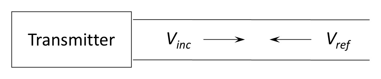
To describe this behavior, it is convenient to consider the voltage waves along the line. Let the wave travelling from the transmitter toward the load be the incident wave, Vinc , and the reflected wave travelling in the opposite direction be Vref , as shown in Figure 10.12. Because the voltage peaks may add or cancel depending on their phase, the resulting standing-wave pattern exhibits alternating maxima and minima of amplitude along the line, as illustrated in Figure 10.13.
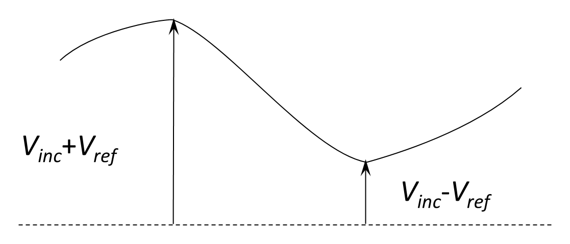
The voltage standing-wave ratio (VSWR) is defined as the ratio of the maximum to the minimum voltage on the line:
For an open or short-circuited line, all of the incident power is reflected, so:
In this case, there is a complete mismatch at the termination and no net power is delivered to the load.
If the line is perfectly matched—that is, the load resistance equals Zo—no power is reflected and all of the energy is absorbed or radiated by the load:
A VSWR of 1 indicates perfect matching, while higher values indicate increasing mismatch. In practical systems, a VSWR of up to about 2 is generally acceptable. Any VSWR greater than 1 means that not all available power is being transferred to the load, so part of the transmitted energy is reflected toward the source.
High reflected power can cause significant losses, generate additional standing-wave interference, and, in high-power systems, damage the transmitter output stage. Modern transmitters often incorporate protective circuits or directional couplers that detect excessive reflected power and automatically reduce drive level to prevent failure.
Because it is easy to measure and directly indicates the degree of matching between line and load, VSWR remains one of the most widely used diagnostics for evaluating transmission-line and antenna performance.
The VSWR therefore ranges from 1 (perfect match) to infinity (complete reflection). In practical systems, values below 2 are generally acceptable. A high VSWR indicates significant reflected power, reduced power transfer efficiency, and potential stress on the transmitter output stage. For this reason, modern transmitters incorporate directional couplers and protection circuits that monitor reflected power and reduce output if necessary.
VSWR is an important measurement as it is simple to measure and gives a good understanding of how well a particular antenna is working.
Back to reading