
10.2.3 Unbalanced Transmission Lines
In an unbalanced transmission line, one conductor is referenced directly to ground (earth), while the other carries the signal with respect to that ground. The return current flows through the grounded conductor or ground plane. Unbalanced lines are widely used in radio-frequency systems because they provide inherent shielding and mechanical robustness, although they may be more susceptible to ground-loop effects if improperly installed.
10.2.3.1 Coaxial Cable
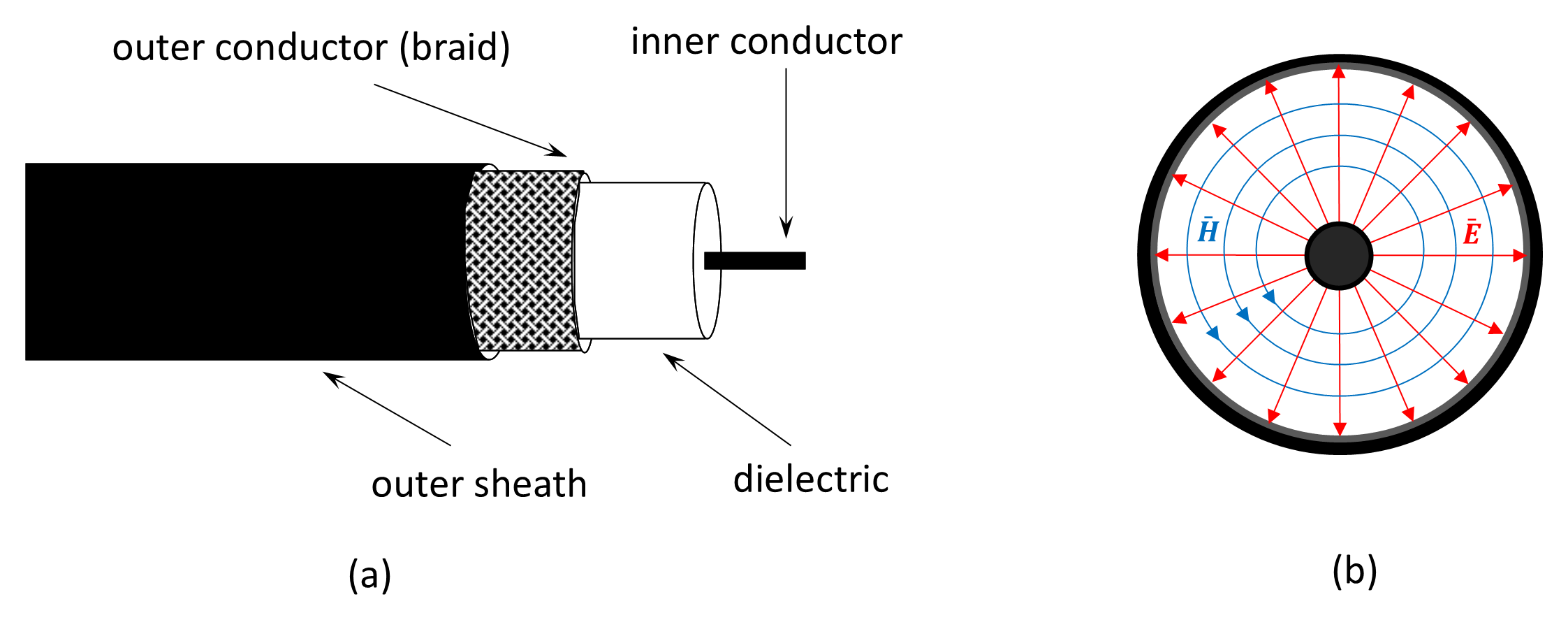
The most common modern form of unbalanced transmission line is the coaxial cable. As illustrated in Figure 10.17, it consists of a central inner conductor surrounded by a cylindrical outer conductor (the shield), separated by a dielectric material. This concentric construction confines nearly all the electromagnetic field to the region between the conductors, greatly reducing radiation losses and susceptibility to external interference, making it suitable for high-frequency and high-power applications. The outer conductor also serves as an electromagnetic shield, preventing coupling from nearby radio-frequency sources and providing a stable ground reference. Because of these properties, coaxial cable is used extensively in radio, radar, instrumentation, and data-communication systems.
Typical coaxial cables operate efficiently from low frequencies up to several gigahertz, depending on construction and dielectric type. Common characteristic impedances are 50 Ω (general communications and RF systems), 75 Ω (video and broadcast applications), 93 Ω (instrumentation), and 300 Ω or 600 Ω (special-purpose or balanced-to-unbalanced feeder systems).
10.2.3.2 Microstrip And Stripline Transmission Lines
At microwave and millimeter-wave frequencies, it becomes impractical to use conventional coaxial cables for interconnections within equipment because of their size, cost, and assembly complexity. Instead, planar transmission lines such as microstrip and stripline are used. These structures are printed directly onto dielectric substrates and form the basis of modern microwave integrated circuits (MICs) and monolithic microwave integrated circuits (MMICs).
Both microstrip and stripline are widely used for filters, couplers, amplifiers, and interconnects in radar, satellite, and wireless communication systems. Their planar form allows compact layout, automated fabrication, and precise impedance control using standard printed-circuit techniques.
A microstrip consists of a flat conducting strip separated from a continuous ground plane by a dielectric substrate. The geometry is unbalanced: one conductor (the strip) carries the signal, while the other (the ground plane) serves as the return path. The electromagnetic field is partly in the dielectric and partly in the air above it, giving an effective permittivity between that of the substrate and free space. Because of this mixed field distribution, microstrip lines exhibit dispersion and slightly frequency-dependent impedance. Typical characteristic impedances lie between 35 Ω and 75 Ω, and microstrip is readily fabricated on materials such as FR-4, PTFE, or alumina.
A stripline consists of a flat conductor sandwiched symmetrically between two ground planes within a uniform dielectric medium. In this configuration, the fields are completely contained within the dielectric, producing a balanced environment (though the line itself remains unbalanced with respect to ground). Stripline offers lower radiation loss and superior isolation between adjacent lines compared with microstrip but is more difficult to manufacture because it requires multilayer substrates.
In summary, microstrip offers simplicity and ease of fabrication but exhibits greater radiation and dispersion due to its partially open structure. Stripline provides superior field confinement and isolation at the expense of increased fabrication complexity and cost.
Back to reading