
10.1.1 Electric Field
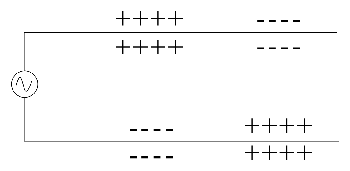
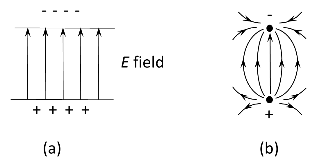
Figure 10.5 shows the instantaneous distribution of charge along the transmission line. If a positive test charge were placed between the conductors, it would experience a force directed toward the region of negative charge, indicating the presence of an electric field (E). The orientation of this field is illustrated in Figure 10.6(a) and in end view in Figure 10.6(b).
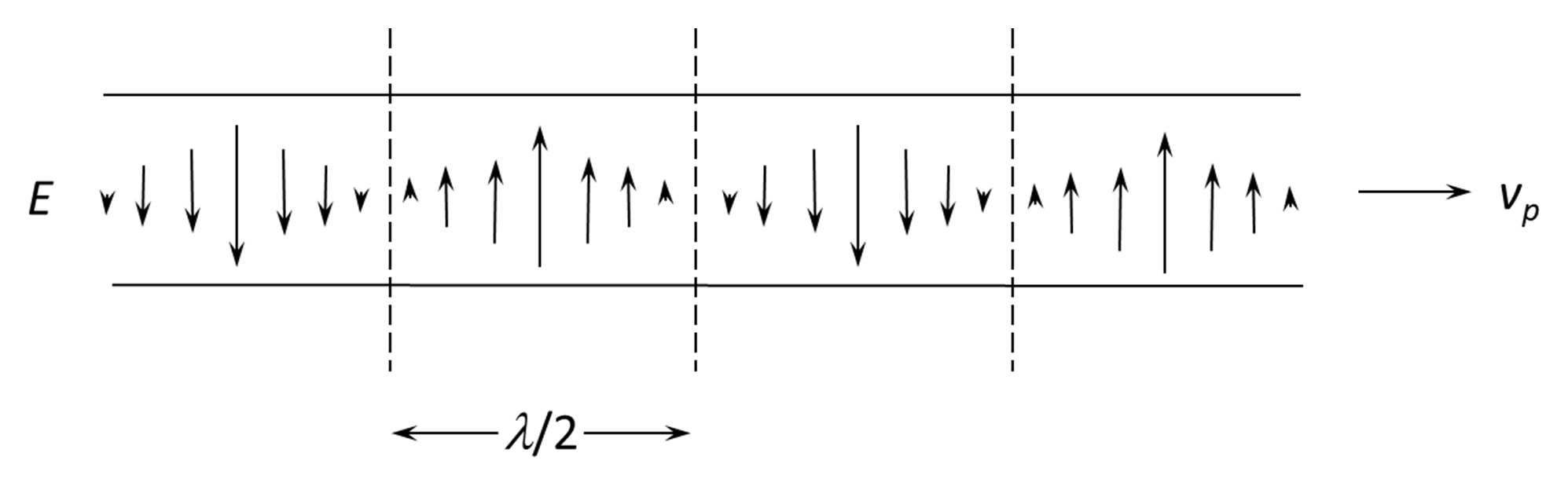
As shown in Figure 10.7, this electric field varies with time and position, forming an alternating E-field that travels between the conductors with the same propagation velocity vₚ (m s⁻¹), wavelength λ (m), and frequency f (Hz) as the associated current and voltage waves described earlier. The E-field represents the means by which energy is transferred along the line and is always accompanied by a corresponding magnetic field (H) that together constitute the electromagnetic wave guided by the transmission-line structure.
The direction of energy flow along the line is given by the Poynting vector, which is perpendicular to both E and H and directed along the axis of propagation. Thus, although current flows in the conductors, the electromagnetic energy itself resides primarily in the fields between them.
Back to reading