
9.2.5 IF Amplifier
The IF amplifier provides most of the receiver’s total gain and selectivity. Typical overall IF gain is 50–70 dB (10⁵–10⁷ times). Operating at a fixed frequency allows the design of sharply tuned, high-Q filters with stable characteristics, ensuring rejection of adjacent-channel interference while preserving the information bandwidth.
The selectivity of a receiver is its ability to discriminate between the wanted signal and adjacent-channel or interfering signals. The IF filters must be narrow enough to reject adjacent channels while remaining wide enough to preserve the highest modulation frequencies without distortion. Because the IF operates at a fixed frequency, sharply tuned, high-Q filters can be implemented with stable and repeatable characteristics.
The shape of the waveform is unchanged by the IF amplifier—but has been amplified, as shown in Figure 9.12. In the case of AM, the information impressed on the carrier has not changed but both carrier and modulation are of greater magnitude which makes the detector’s task easier.
Modern receivers increasingly implement IF filtering using crystal, surface-acoustic-wave (SAW), ceramic, or digital filters, offering bandwidth control and programmable selectivity. In SDRs, the IF may even be zero (direct conversion) and filtering is entirely digital.
9.2.5.1 Choice Of IF
As outlined earlier, the difference frequency generated by the mixer is chosen as the IF. The sum frequency component is not chosen as the IF because it would mean that the IF would have to be greater than the highest frequency in the tuning range of the receiver. The main factors to be considered when choosing the IF are the required IF bandwidth, the interference signals that must be handled by the receiver, the required IF gain and stability, and the required adjacent channel selectivity. The choice of IF is a compromise between the following, often conflicting, factors:
- A high IF allows the image channel to be rejected more easily but causes tracking difficulties and leads to poor selectivity and poor adjacent-channel rejection.
- A low IF simplifies the design and construction of the IF amplifier.
- Adjacent-channel selectivity is easier to obtain using a low IF, although a higher IF is required to achieve a larger bandwidth.
- A low IF requires a more stable LO since any tracking error will be a greater proportion of a low IF.
- The IF must not fall within the tunable range of the receiver to avoid IF breakthrough.
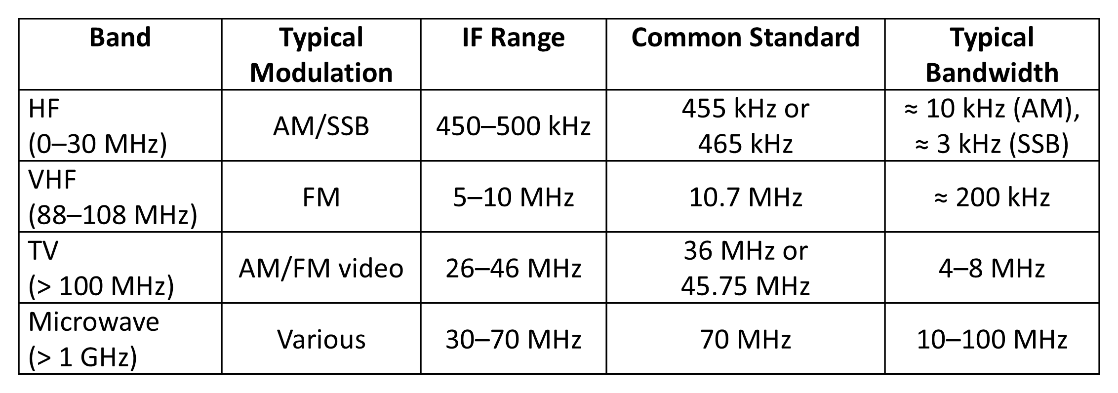
Over many years these requirements have coalesced to the standard IF values in Figure 9.14.
9.2.5.2 Modern IF Approaches
While the superheterodyne design remains the basis of most analogue receivers, rapid advances in semiconductor integration and digital signal processing have produced new receiver architectures that extend its principles into the digital domain. These designs achieve superior linearity, frequency agility, and selectivity while reducing component count and calibration requirements.
Double- and Triple-conversion Receivers
Multi-conversion architectures are often required to distribute image rejection, selectivity, and gain across several frequency translations, allowing each IF to be optimized for a specific purpose—high first IF for image rejection, lower subsequent IFs for narrow-band filtering and stable gain control. If multiple amplification stages are required, it is more common to see one RF stage and multiple IF stages than it is to have multiple RF stages.
Commonly, two or three IFs (double or triple conversion) are used to balance these conflicting requirements in IF selection, particularly in high-performance HF, VHF, and microwave receivers where image isolation greater than 90 dB and dynamic ranges above 100 dB are required. When a receiver has two IFs, it is called a double-conversion receiver. The first IF is high for image rejection; the second is low for selectivity (narrow-band filtering and stable gain control).
Zero-IF (Homodyne) Receivers
In a zero-intermediate-frequency (zero-IF) or homodyne receiver, the RF signal is mixed directly to baseband using in-phase (I) and quadrature (Q) channels. This architecture eliminates IF filters, simplifies tuning, and allows fully digital processing after the first down-conversion. However, it introduces new design challenges, including DC offsets, I/Q imbalance, and LO leakage. Modern implementations correct these impairments dynamically using on-chip calibration and digital feedback loops.
Back to reading