
9.2.1 Basic Design
In its simplest form, the receiver is a means by which the received electromagnetic energy is transferred into audio frequencies. The block diagram for a simple AM receiver is shown in Figure 9.8, which is the basis of the simple crystal radio set that dates back to the early 1900s. The incident electromagnetic field from the transmitter induces a current in the receiving antenna (the coupling mechanism is examined in Chapter 12). The tuned circuit selects the desired carrier frequency, and a detector—typically a crystal diode—rectifies and demodulates the signal to recover the audio component that is reproduced in earphones, as shown in Figure 9.9.
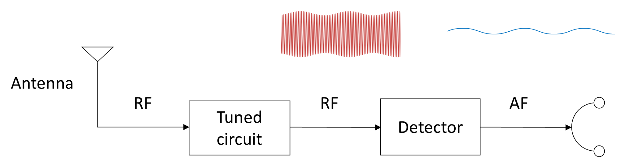
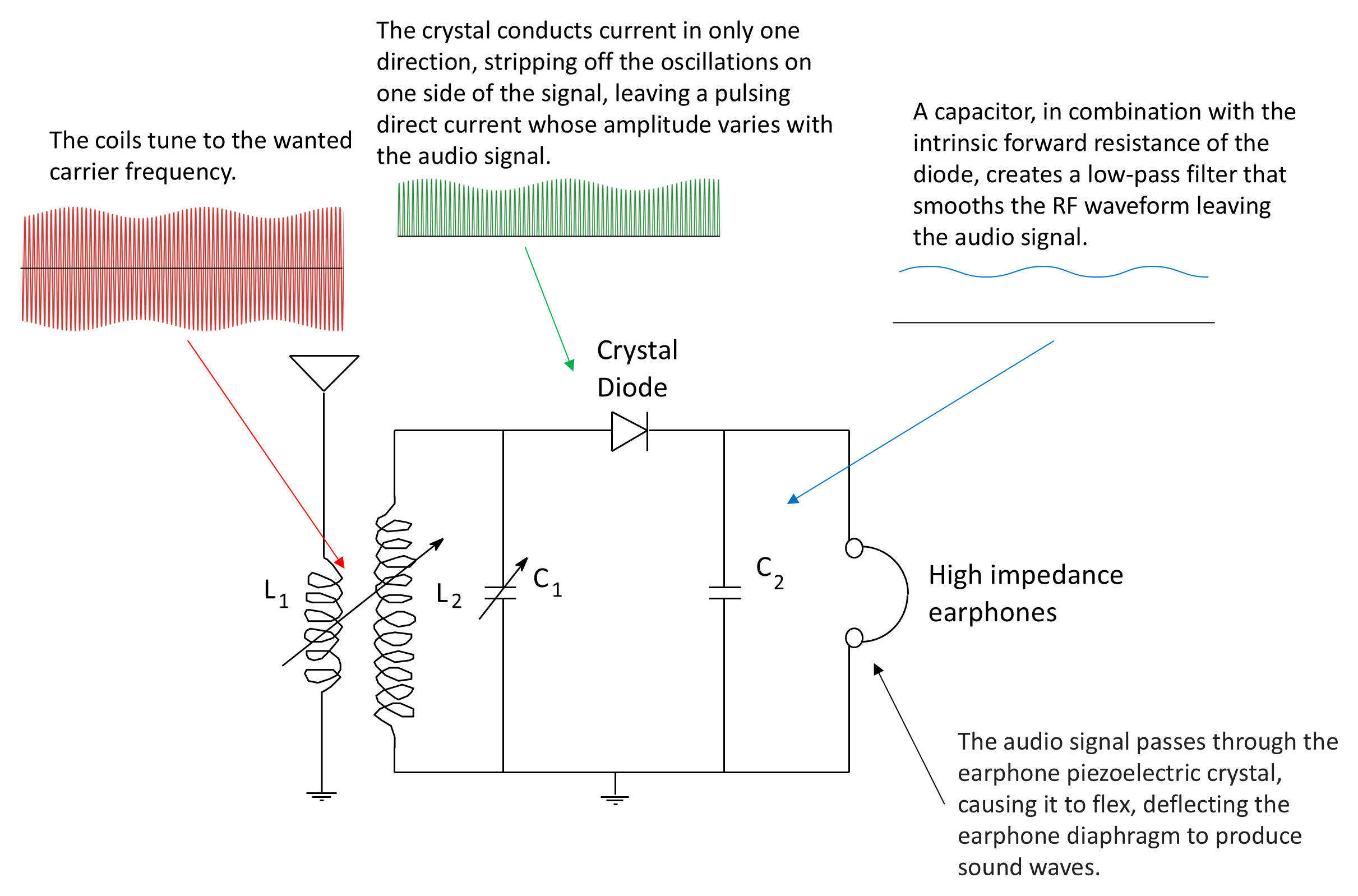
Because the circuit contains no active amplification, it requires relatively large incident signals and can detect only powerful local transmission, which generally means that the range of communication is small. The available audio output is also insufficient to drive a loudspeaker, so headphones are essential. Consequently, communication range is limited, audio output is insufficient to drive a loudspeaker, and both sensitivity and selectivity are poor. Inadequate filtering allows adjacent frequencies to be received simultaneously.
Practical systems require amplification to make weak signals intelligible. When amplification is introduced at RF, sensitivity improves dramatically—often by many orders of magnitude—and selectivity also improves because the effective bandwidth of the tuned circuit narrows. Additional amplification at audio frequencies following detection allows loudspeaker operation.
In an RF tuned circuit, the quality factor Q depends on the ratio of reactance to resistance:
where XL is inductive reactance and R represents the effective resistance losses in the circuit.
Note that a lower circuit resistance produces a higher Q. The bandwidth (BW) of the tuning circuit will decrease with an increase in Q:
where fo is the center frequency to which the circuit is tuned.
In practical active RF stages, amplification reduces the effective loading of the tuned circuit and can compensate for resistive losses, thereby increasing the effective Q. As Q increases, bandwidth decreases, and selectivity improves. Additional amplification at audio frequencies following detection enables loudspeaker operation.
9.2.1.1 Tuned Radio-Frequency (TRF) Receiver
The receiver shown in Figure 9.10 adds RF and AF amplification stages to the crystal set. This tuned radio-frequency (TRF) receiver, widely used in the early 1920s, enabled reception of weaker signals and eliminated the need for headphones. Despite its simplicity, the TRF configuration suffers several important drawbacks.
The primary disadvantage is that its bandwidth is not constant over a wide tuning range. For a constant Q, Equation (9-4) shows that bandwidth increases with center frequency. Consequently, as the receiver is tuned upward in frequency, its bandwidth increases proportionally, reducing selectivity. One contributing factor to this behaviour is the skin effect. At radio frequencies, current flows primarily near the surface of a conductor. As frequency increases, the effective conducting area decreases, increasing the effective resistance of the inductor windings. Any increase in effective resistance influences the attainable Q.
A second major disadvantage is instability. TRF receivers often employ several RF amplifiers tuned to the same center frequency. High-frequency multistage amplifiers are inherently susceptible to unintended feedback through stray capacitances and coupling paths. When the loop gain exceeds unity at some frequency, the amplifier can break into oscillation, effectively becoming an unwanted transmitter. One partial mitigation technique is stagger tuning, in which successive RF stages are tuned to slightly different center frequencies—some slightly above and some slightly below the nominal carrier frequency. This broadens the composite response and improves stability, but at the expense of additional complexity and imperfect overall response shaping.
A third disadvantage is that gain is not uniform across a wide tuning range. Transformer-coupled tank circuits in the RF amplifiers exhibit varying L/C ratios as they are tuned. Because inductance and capacitance do not scale uniformly with frequency, the gain–frequency response changes across the band. Consequently, sensitivity varies with tuning frequency.
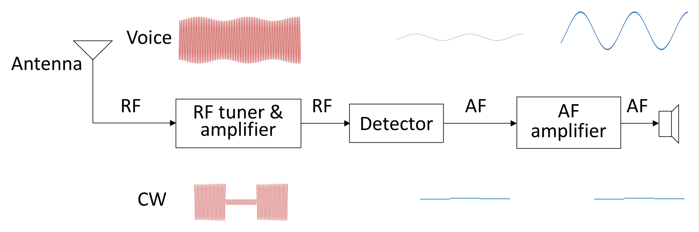
The TRF receiver is also unsuitable for the reception of continuous-wave (CW) Morse signals. In CW transmission, the carrier is simply switched on and off. A TRF receiver detects only the envelope of the signal, so the output consists merely of clicks corresponding to carrier transitions. The operator cannot hear an audible tone. To make Morse signals audible, the RF carrier must be mixed with a locally generated frequency to produce an audible beat note. This requirement leads directly to the heterodyne principle.
9.2.1.2 Heterodyne Receiver
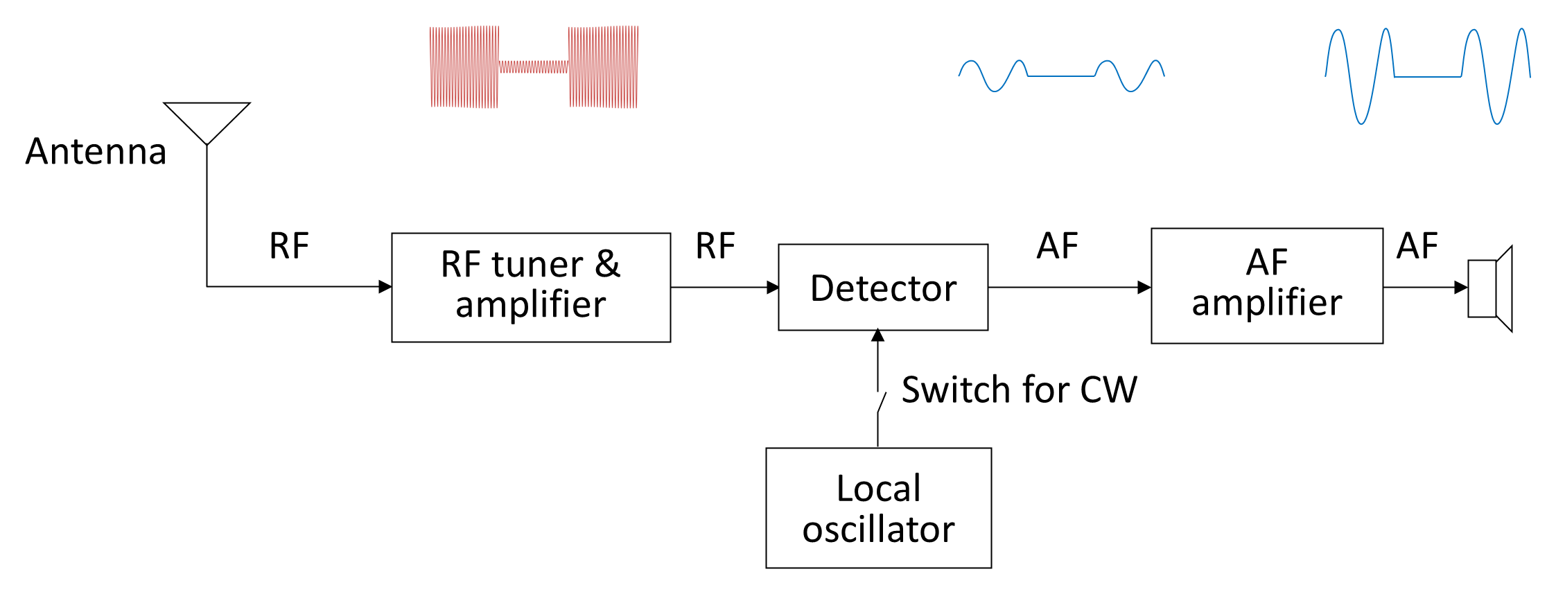
To render Morse signals audible, variations in the RF carrier must be converted into variations within the audio frequency range. Such a receiver is called a heterodyne receiver from the Greek heteros (different); and dynamis (power), referring to the production of new frequencies by mixing two signals.
As shown in Figure 9.11, the incoming RF signal is mixed with a local oscillator (LO) whose frequency differs slightly from the carrier frequency. If the LO is tuned 1 kHz above the carrier, mixing produces a 1 kHz difference frequency in the audio range, allowing Morse signals to be heard as tones. The oscillator can be switched out when receiving standard AM signals.
Although the TRF receiver is relatively simple to implement at broadcast frequencies (up to approximately 1.5 MHz), its sensitivity and selectivity remain inadequate for higher frequencies and longer ranges. As previously shown, bandwidth increases with frequency for constant Q, making uniform selectivity difficult to achieve.
Large amounts of RF amplification would be required to compensate, but the number of RF stages is practically limited to three or four due to cumulative noise, instability, and oscillation risks. Additionally, bandwidth varies significantly across the tuning range.
It is therefore not possible for the RF stage alone to provide high amplification, stable operation, uniform bandwidth, and consistent selectivity across a wide frequency range. These conflicting requirements can only be met by addressing them in different stages within the receiver. The solution is to extend the heterodyning notion to a superheterodyne receiver (super meaning over or above).
The superheterodyne receiver was developed by Major Edwin H. Armstrong in 1918 while serving in the US Army Signal Corps during the First World War. Armstrong’s innovation revolutionized radio receiver design by introducing frequency conversion to a fixed intermediate frequency, enabling stable high gain and constant bandwidth independent of the received carrier frequency. Nearly all modern radio receivers—analogue and digital—retain this fundamental architecture.
9.2.1.3 Superheterodyne Receiver
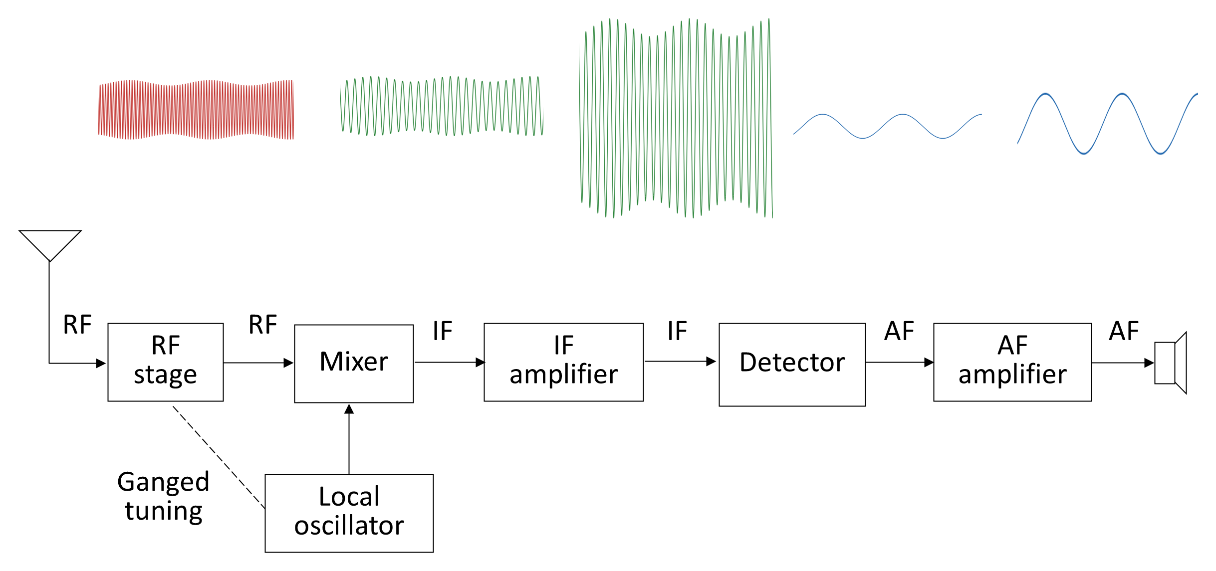
The basis of a superheterodyne receiver is the translation of the wanted signal frequency into a constant IF at which most of the gain and the selectivity of the receiver is provided without affecting the bandwidth. As shown in Figure 9.11, the incoming RF is mixed with an LO whose frequency differs from the desired signal by the IF value. The resulting difference frequency—the IF—contains the same modulation as the original RF but at a lower, constant frequency.
The IF stages provide stable gain and well-defined selectivity, while the RF front end supplies pre-selection and image-frequency rejection. To ensure that the result of the mixing is always the IF, the tuning of the RF amplifier and LO must track together, usually by means of ganged tuning capacitors or, in modern equipment, phase-locked frequency synthesizers (see Section 9.2.3 for more detail). For the moment, note that the RF stage and the local oscillator need to be tuned separately depending on the incoming frequency and that it would be convenient to do this with a single control.
The superheterodyne design remains the foundation of nearly all modern analogue receivers because it provides high sensitivity, constant bandwidth, and excellent adjacent-channel rejection.
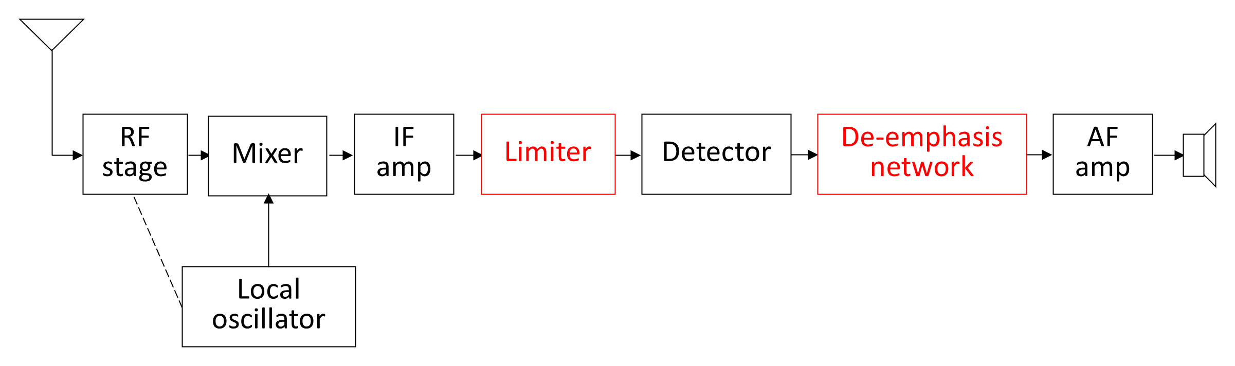
The superheterodyne receiver of Figure 9.12 is suitable for AM signals. The FM receiver has a very similar structure except of course that, due to the different modulation, the detector circuit will be different. Additionally, as shown in Figure 9.13, an FM receiver has two further circuits: a limiter and a de-emphasis network.
- Limiter. The purpose of the limiter is to remove any residual amplitude variations in the signal before it reaches the detector, ensuring that amplitude noise does not translate into baseband distortion. Any AM noise that may have become part of the signal therefore does not affect the information that is contained in the frequency variations.
- De-emphasis network. The de-emphasis network is the second half of the pre-emphasis/de-emphasis system described in Section 9.1.2. The pre-emphasis network amplified the higher-frequency information content of the audio signal at the transmitter more than the lower-frequency information. The de-emphasis network compensates for this by reducing the gain of the higher-frequency audio signal thereby reducing frequency-modulated noise. These pre-/de-emphasis time constants are standardized internationally (e.g., 75 µs in North America, 50 µs in Europe).
The remaining stages of the superheterodyne receiver are similar for the AM and FM receiver. Having established the superheterodyne principle, the following sections examine each functional stage in signal-flow order: RF front-end conditioning, local oscillator generation, frequency conversion in the mixer, intermediate-frequency amplification and filtering, detection, automatic gain control, and finally audio-frequency amplification and output conditioning.
Back to reading