
9.1.2 FM Transmitters
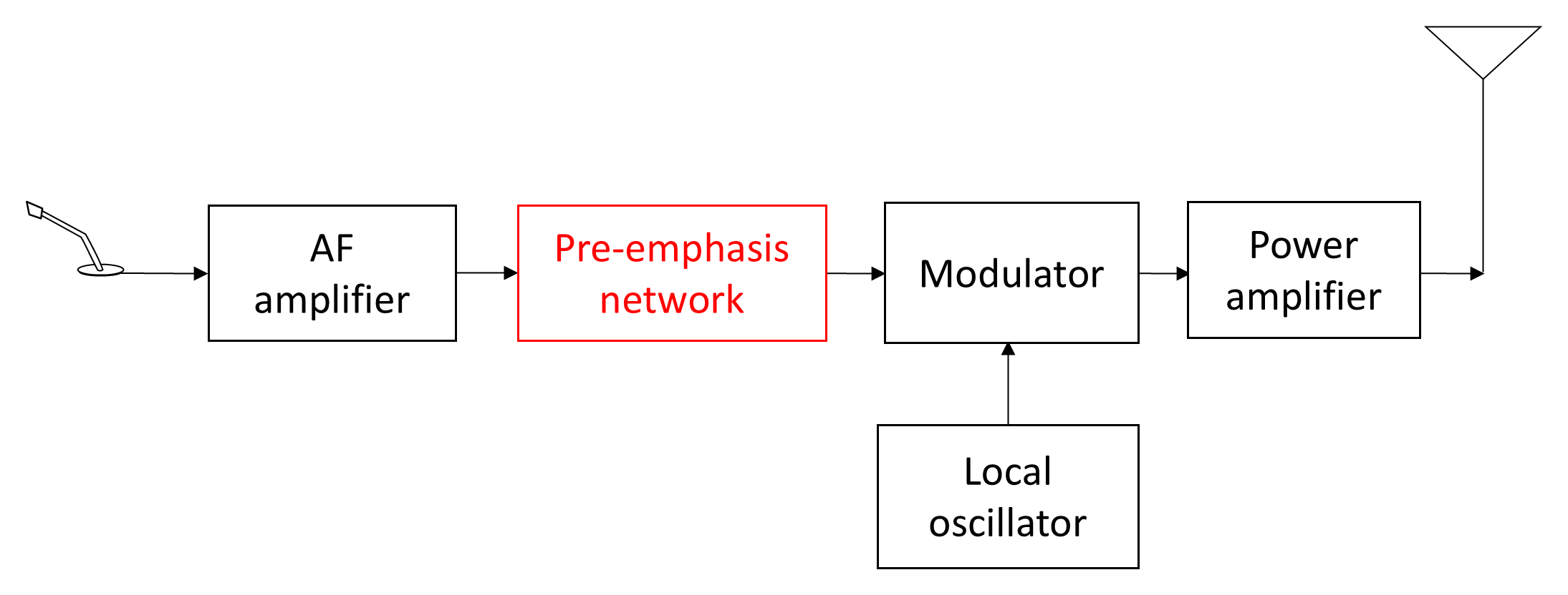
An FM transmitter (Figure 9.5) closely resembles a low-level AM transmitter but includes an additional pre-emphasis network. This forms one half of the pre-emphasis/de-emphasis system used to reduce frequency-modulated noise (see Section 6.2.2.9). Because the noise power at the output of an FM detector increases with frequency at approximately 6 dB per octave, high-frequency audio components are most affected. The pre-emphasis network in the transmitter boosts these higher-frequency components before modulation, while the receiver’s de-emphasis network (Figure 9.6) applies the complementary attenuation, thereby flattening the overall response and improving intelligibility.
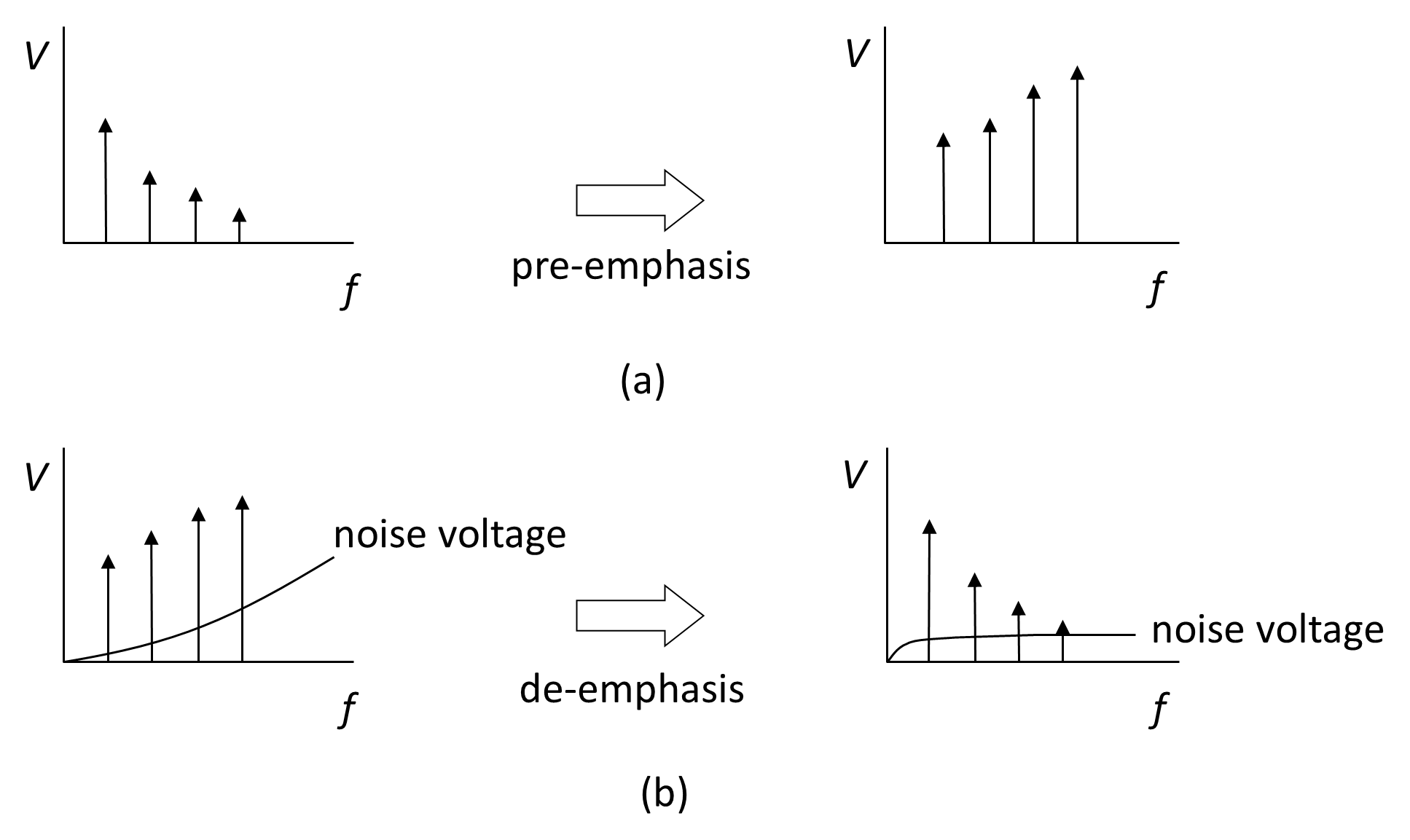
In modern digital systems, similar noise-weighting is achieved digitally through companding or perceptual weighting algorithms that achieve similar noise-reduction benefits. The underlying concept—pre-compensating a signal for expected channel or detector behavior—remains the same.
There are two types of methods for generating an FM signal, the direct method and the indirect method.
- Direct method. A reactance circuit, whose effective capacitance or inductance varies with the amplitude of the modulating signal, is connected to a variable-frequency local oscillator. Variations in reactance alter the oscillator frequency in proportion to the modulating signal. Because the frequency-determining components must be tunable, crystal oscillators cannot be used directly; automatic frequency control (AFC) is required to stabilize the LC oscillator.
- Indirect method. Higher frequency stability is achieved by first generating a phase-modulated (PM) signal and integrating the modulating signal to yield an equivalent FM waveform. This approach permits the use of stable crystal-controlled oscillators.
Frequency deviations generated at low IFs (typically 30–100 Hz) are increased to the required level (e.g., ±75 kHz for FM broadcast) through frequency multiplication. The carrier frequency of a frequency-modulated signal is:
Multiplying this frequency by a factor M produces a new signal with a center frequency of Mfc and a frequency deviation of MΔf. That is:
Modern FM systems frequently employ direct digital synthesis (DDS) or fractional-N phase-locked loops (PLLs) to produce highly stable, low-phase-noise FM signals without analogue multipliers [2].
Endnotes
- [2] Best, R. E., Phase-Locked Loops: Design, Simulation and Applications, 7th ed., McGraw-Hill, 2023. back