
9.1.1 AM Transmitters
In an AM transmitter, frequency translation is accomplished by amplitude-modulating an information signal onto a carrier generated by a highly stable local oscillator. The modulated waveform is then amplified to the required radiated power. Although AM transmitters were historically used for broadcast and aeronautical applications, the same principle underlies many digital amplitude/phase modulation formats—such as quadrature amplitude modulation (QAM) and amplitude-phase shift keying (APSK)—used in modern digital systems.
There are two classical architectures for AM transmitters—low-level and high-level—depending on whether modulation occurs before or after power amplification.
9.1.1.1 Low-Level Transmitters
In the low-level configuration (Figure 9.1), the carrier voltage from the local oscillator is not power-amplified prior to modulation. The relatively weak audio signal is first strengthened by an audio-frequency (AF) amplifier before modulation. Low-level modulation is convenient for square-law modulators and for systems requiring extensive filtering—such as single-sideband (SSB) and independent-sideband (ISB) transmitters—since it is far easier to implement precise filters at low power.
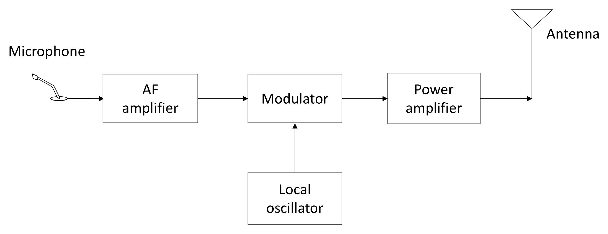
Low-level AM techniques also correspond conceptually to the digital baseband domain in contemporary transmitters, where in-phase (I) and quadrature (Q) components are digitally filtered before RF up-conversion.
9.1.1.2 High-Level Transmitters
A principal disadvantage of the low-level approach is that substantial linear amplification is required after modulation to reach the final output power. Because linear RF power amplifiers are complex and inefficient, high-level modulation (Figure 9.2) is often preferred. In this method, both the audio signal and the carrier are independently amplified to the required level before modulation. This allows efficient use of non-linear RF amplifiers for the carrier, at the cost of requiring high-power AF amplifiers.
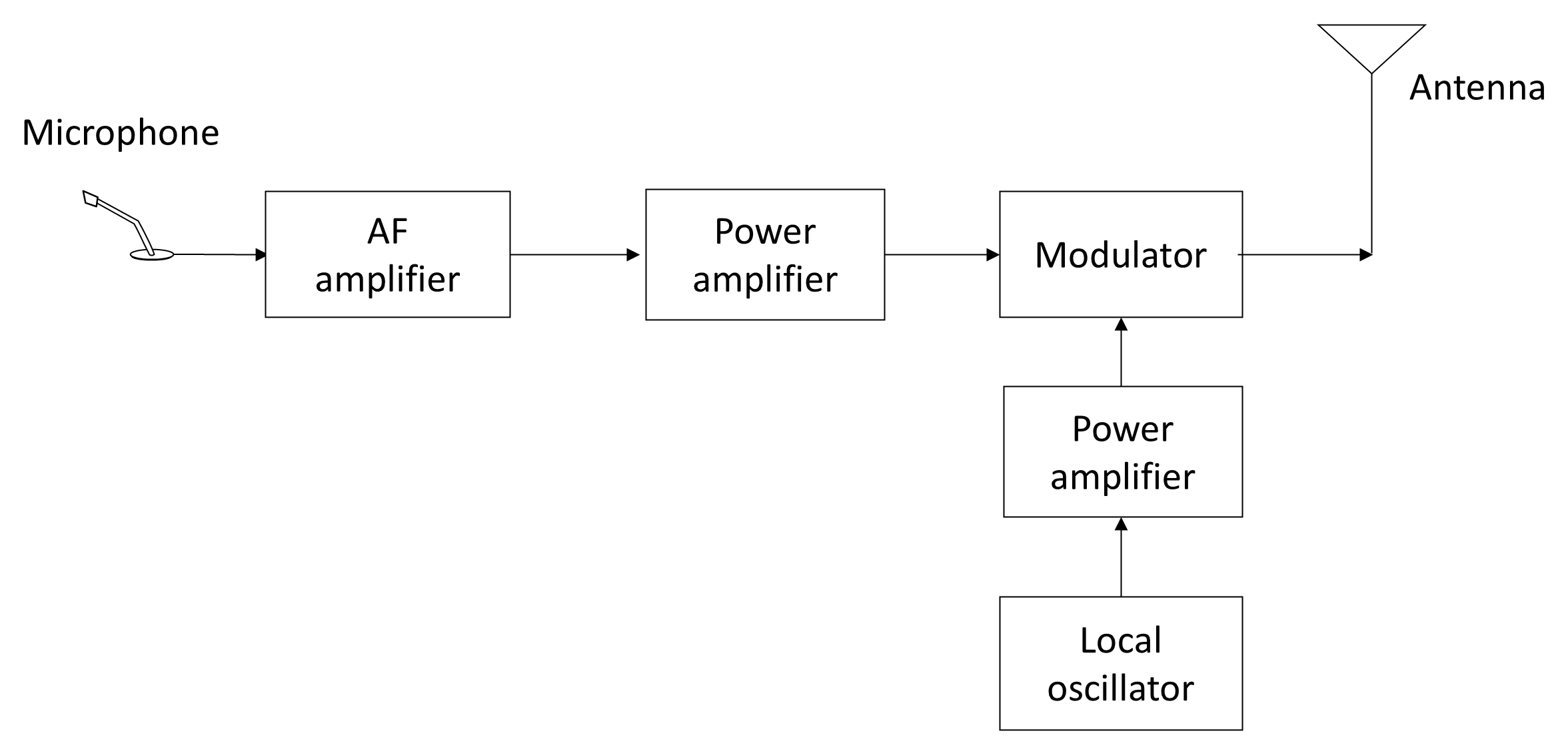
At moderate power levels, the efficiency advantage of high-level modulation has traditionally been exploited in VHF/UHF mobile transmitters. In modern systems, however, amplitude information is imposed digitally, and digital predistortion (DPD) and envelope-tracking (ET) techniques are employed to linearize inherently non-linear RF devices such as Class F or Doherty amplifiers, thereby achieving high efficiency with low distortion.
9.1.1.3 Drive Units
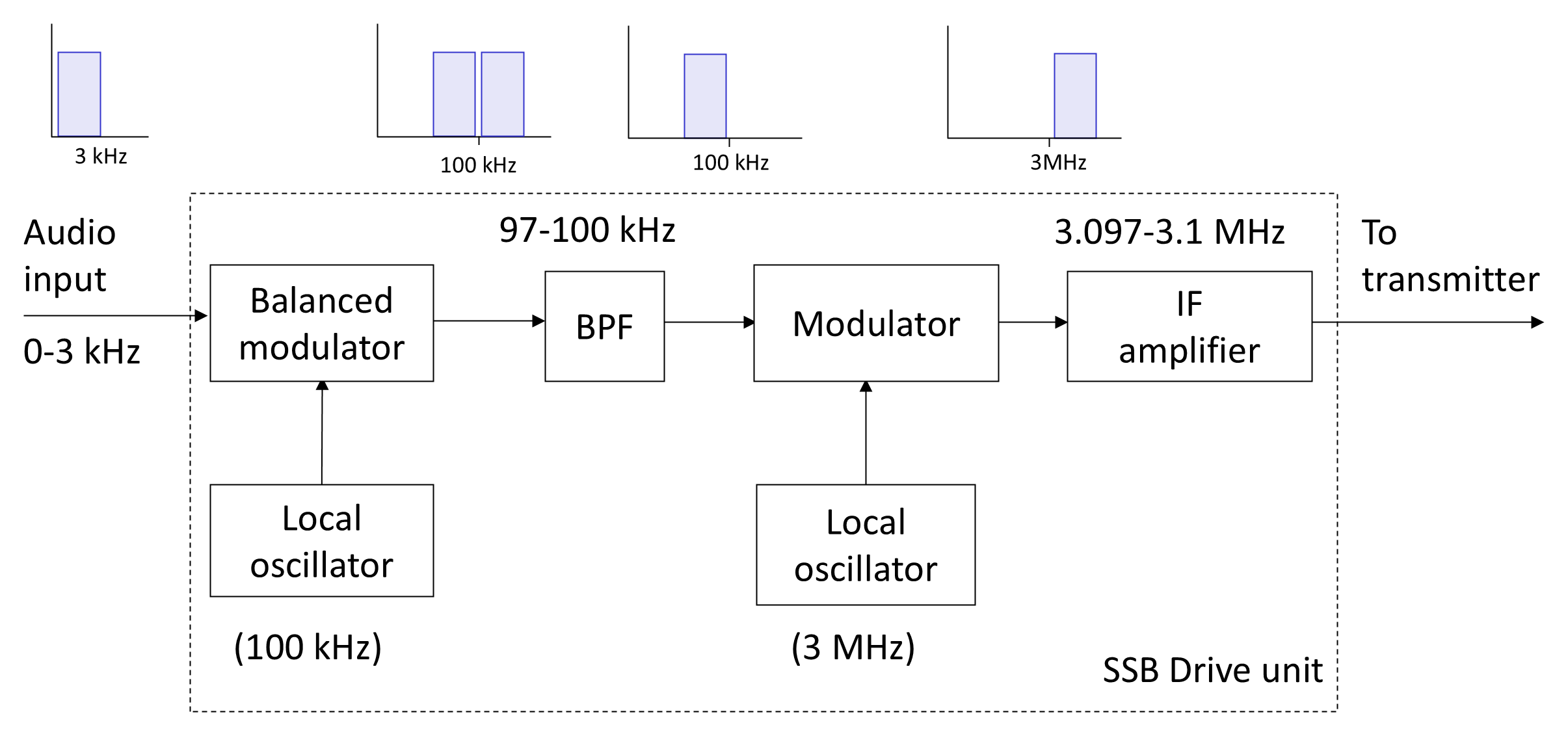
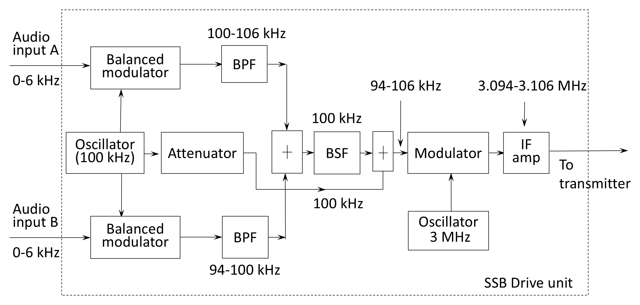
In many classical AM, SSB, and ISB transmitters, modulation occurs in a separate drive unit that produces a standard intermediate-frequency (IF) output for subsequent up-conversion and power amplification.
- SSB drive unit. A typical SSB drive unit (Figure 9.3) uses balanced modulation to suppress the carrier, followed by band-pass filtering to select the desired sideband.
- ISB drive unit. An ISB drive unit (Figure 9.4) accepts two audio inputs (A and B), each applied to a balanced modulator with a common 100-kHz carrier. The upper sideband of channel A and the lower sideband of channel B are selected by band-pass filters (BPF) and combined to form a 97–103 kHz composite signal, which is then translated to 3.097–3.103 MHz by mixing with a 3-MHz carrier. The drive-unit output is fed to the main transmitter for amplification and final frequency conversion.
In modern digital systems, these analogue processes are performed numerically: SSB and ISB generation are implemented in digital up-conversion (DUC) stages using finite-impulse-response (FIR) or polyphase filters. The drive unit concept survives as the digital front-end (DFE) of a software-defined transmitter [1].
Endnotes
- [1] Mitola, J., Software Radio Architecture, New York, NY: Wiley, 2000. back