
11.6.1 Troposcatter Communications
Tropospheric scatter (troposcatter) communication enables reliable beyond-line-of-sight (BLOS) radio transmission by exploiting forward scattering from refractive-index irregularities in the lower troposphere. Unlike conventional microwave line-of-sight systems, which require geometric visibility between terminals, troposcatter systems direct narrow high-gain antenna beams toward a common scattering volume located just beyond the radio horizon. A small fraction of the transmitted energy is scattered forward and intercepted by the distant receiving antenna.
Tropospheric scatter communication emerged in the late 1940s and early 1950s following post-war investigations into beyond-line-of-sight radio propagation. Experimental work demonstrated that measurable signal energy could be received well beyond the geometric radio horizon at VHF and UHF frequencies. By the mid-1950s, operational troposcatter systems were deployed for long-distance military communication links, particularly in regions where terrain or political constraints made construction of line-of-sight relay chains impractical.
During the Cold War, large fixed troposcatter networks formed part of strategic communication infrastructure, especially in remote and high-latitude regions. These systems commonly operated between a few hundred megahertz and several gigahertz, employed high-power transmitters (often several kilowatts), and used very large parabolic antennas—frequently 10–30 m in diameter. Analogue FM transmission supported multichannel voice using FDM techniques. Dual or quad diversity reception became standard practice to mitigate severe fading.
With the rapid expansion of satellite communications from the 1970s onward, troposcatter declined in mainstream commercial long-haul telecommunications. Geostationary satellite systems offered greater capacity and simplified deployment over continental distances. However, troposcatter remained attractive for specialised applications because it requires no space segment, offers inherent survivability, and presents a lower probability of interception than satellite links.
Modern troposcatter systems employ digital modulation schemes (e.g., PSK and QAM), forward error correction, adaptive coding, and advanced diversity techniques. They support broadband data rates ranging from several megabits per second to tens of megabits per second, depending on path length and fade margin. Contemporary applications include:
- Military and tactical communications where resilience and satellite independence are required.
- Remote infrastructure links (e.g., oil platforms, mining sites, polar installations).
- Emergency and disaster-recovery networks.
- High-latitude regions where satellite elevation angles are low.
Thus, while troposcatter is no longer a dominant long-haul medium, it remains an important specialised technology for resilient beyond-line-of-sight terrestrial communication.
11.6.1.1 Physical Basis Of Tropospheric Scattering
Figure 11.25 illustrates the scattering mechanism for troposcatter. The transmitter radiates at a low elevation angle toward the lower troposphere, illuminating a common atmospheric volume just beyond the geometric radio horizon. No specific discrete reflection point is targeted; rather, scattering occurs throughout the illuminated volume. Much of the transmitted energy is lost through scattering in undesired directions and atmospheric absorption, but a small forward-scattered component reaches the receiving antenna.
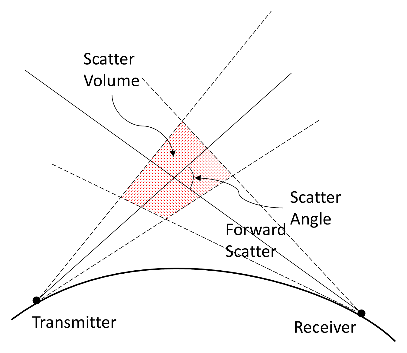
The troposphere contains continual small-scale fluctuations in refractive index caused by spatial variations in temperature, pressure, and humidity. Turbulent variations in refractivity create randomly distributed scattering centers. When a narrow microwave beam illuminates a volume of atmosphere beyond the horizon, irregularities within that volume scatter energy in multiple directions. The received signal is the vector sum of numerous scattered contributions.
The received power depends strongly on:
- Scatter angle (smaller angles produce higher received levels),
- Path length (loss increases rapidly with distance),
- Frequency (loss increases with frequency),
- Refractive turbulence intensity,
- Height of the common volume,
- Antenna beamwidth and gain.
Because the scattering process is statistical rather than specular, troposcatter signals exhibit both short-term fading (seconds to minutes) and long-term fading (hours to days). Deep fades of 20–40 dB relative to the median level are common. Diversity techniques are therefore essential and may include:
- Frequency diversity: transmitting the same information simultaneously on multiple frequencies.
- Space diversity: using physically separated antennas.
- Time diversity: transmitting redundant information at different times.
11.6.1.2 Basic Propagation Loss
To establish a link budget, it is useful to begin with the free-space attenuation between isotropic antennas:
where f is the frequency of operation in MHz and d is the path length in kilometers.
Troposcatter introduces an additional scattering loss component. The sum is termed the basic propagation loss (BPL):
Empirical measurements show that scattering loss introduces additional frequency dependence beyond the free-space term. The total frequency dependence of BPL is approximately proportional to:
Thus, each doubling of frequency increases basic propagation loss by approximately 9 dB.
The basic propagation loss assumes antennas are aimed tangentially to a smooth Earth (zero horizon angle). In practice, terrain may require antennas to be elevated above the tangent line; a maximum elevation of approximately 5° is a typical deployment rule of thumb. The horizon angle at each terminal is the elevation angle required to clear terrain obstructions.
Positive horizon angles increase the scatter angle, raise the height of the common volume, and increase scattering loss. Negative horizon angles (sites elevated above surrounding terrain) reduce scatter angle, lower scatter volume height, and reduce total loss. The additional loss depends primarily on the sum of the horizon angles at the two terminals. For shorter paths, the fractional effect is more pronounced.
Modern statistical modelling of trans-horizon paths may use ITU-R Recommendation P.452 and related guidance for tropospheric-scatter prediction.
11.6.1.3 Aperture-To-Medium Coupling Loss
Large parabolic antennas concentrate energy toward the common volume. As antenna gain increases and beamwidth narrows, the illuminated scatter volume decreases. This reduction introduces aperture-to-medium coupling loss, which increases with combined antenna gain and path length. In simplified empirical form the additional loss is:
where GT and GR are the transmit and receive antenna gains (dBi).
Very large apertures (exceeding roughly 30 wavelengths) may incur additional multipath cancellation loss due to partial out-of-phase summation of scattered components.
11.6.1.4 Typical Troposcatter Systems
Practical single-hop troposcatter links typically span 150–500 km. Under favorable atmospheric and terrain conditions, paths of 800–1,000 km are achievable, though with substantial fade margins and diversity requirements.
Frequencies between approximately 300 MHz and 5 GHz are commonly used. Early systems employed analogue FM in bands such as 345–988 MHz and supported 6–120 voice channels using 4-kHz FDM. Modern systems employ digital modulation schemes such as PSK or QAM with forward error correction and adaptive coding, supporting data rates of tens of megabits per second depending on system design and path conditions.
Because only a minute proportion of transmitted energy is captured after scattering, path attenuation is extremely high. Combined free-space and scattering losses typically lie between 190 dB and 240 dB for medium-length paths. Reliable operation therefore requires: high EIRP, large high-gain antennas, low receiver noise figure, and diversity techniques to combat fading.
Troposcatter systems operate primarily in the UHF and lower microwave bands, typically between about 300 MHz and 5 GHz. Reliable operation therefore requires high EIRP, large high-gain antennas, low receiver noise figure, and diversity techniques.
Typical applications include:
- Connecting remote sites.
- Linking islands to mainland.
- Connecting offshore oil and gas platforms to shore.
- Crossing unsecured or inaccessible terrain.
- Providing large networks spanning long distances with minimal intermediate infrastructure.
11.6.1.5 Advantages And Disadvantages Of Troposcatter Systems
From an operational perspective, the most significant advantage of troposcatter is the ability to achieve reliable beyond-line-of-sight communication without intermediate repeaters. Other advantages include:
- Terrain has little effect on propagation.
- Long hop length requiring few repeaters.
- Reduced infrastructure.
- Inherently survivable.
- Less susceptible to interception.
- Low vulnerability to jamming.
- Independent of satellite systems.
The principal disadvantages are:
- Higher cost per station (although total system cost may be lower due to fewer sites).
- High-gain antennas are difficult to orientate (although phased array antennas may mitigate this).
- Requires unobstructed view of horizon (practical maximum of a 5° take-off).
- High power requirements with associated RF hazard.
- Potential frequency re-use constraints on long paths.