
11.3.3 Equivalent Radius Of The Earth
Before looking at the loss factors, we need to understand the effect that the atmosphere has on the propagation of the wave. In an atmosphere with a uniform refractive-index profile, radio waves would travel in a straight line and the range would be limited to the geometric horizon due to the curvature of the Earth. The optical horizon (dgeometric) can be determined by:
where dgeometric is in km and hT and hR are the heights in meters of the transmit and receive antennas above the surface of the Earth.
The density of the Earth’s atmosphere is not uniform, however, and the refractive index decreases with height. As it travels through the atmosphere, a radio wave experiences a gradual refraction towards the ground. This gentle bending of the radio path towards the Earth increases the range of communications beyond the geometric horizon. This is an advantage in that it extends communications by several kilometers, but it does present a number of difficulties when trying to plot the radio path to determine the radio line-of-sight. To solve these difficulties a correction factor k is used to increase the radius of the Earth such that the effective radius of the Earth, re, is assumed to be:
where ra is the actual radius of the Earth (6,378 km). As shown in Figure 11.9, this compensates for the refraction and the radio path can be shown as a straight line between antennas.
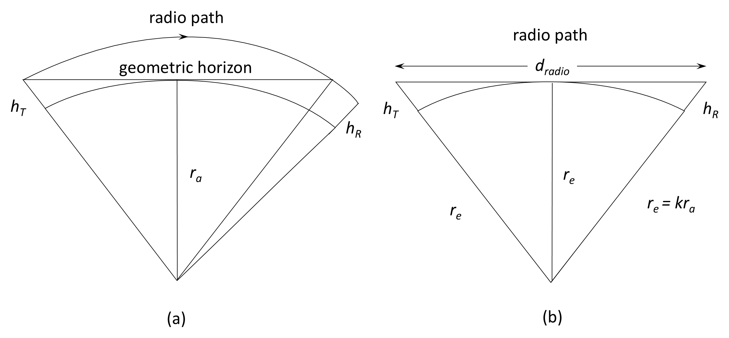
The value of k depends on a number of factors and, even under normal weather conditions, it fluctuates over a range of values. This means that the height of the direct path above the Earth’s surface varies slightly—typically several meters over moderate path lengths. Such variations are seldom significant at VHF and lower UHF so the ITU-R standard atmosphere is assumed and a value of k=4/3 is used. At SHF, however, such variations can have a significant effect, and a more pessimistic view is taken and k=1 is used. For k=4/3, specially corrected paper is available to plot path profiles on the corrected Earth radius.
The radio horizon can now be determined geometrically as:
where dradio is in kilometers and hT and hR are in meters. A factor of k=4/3 is assumed. The radio horizon is therefore slightly further than the optical horizon.
Example 11.1
For a 10-m transmitting mast and a 5-m receiving mast, calculate (a) the optical horizon and (b) the radio horizon.
(a)
(b)
Abnormal refraction. The theory of duct formation is outside the scope of this book, but it should be noted that, under certain weather conditions, very large values of k (up to about 3.0) can cause radio waves to follow the Earth’s surface for long distances. Such conditions occur mostly over sea or coastlines, when the air in contact with the surface is cooler than the air above (a temperature inversion). These conditions are also met in the daytime over tropical areas and occur over deserts at night when the ground has cooled quickly. The phenomenon is called super-refraction. Opposite conditions can lead to the radio wave being bent upwards; called sub-refraction. Elevated ducts can also form between two layers in the atmosphere or between the ionosphere and the Earth's surface. Radio waves may be trapped in these ducts and either give no signal at the receiver or produce unusually long-range propagation.
Back to reading