
11.5.3 The Best Frequency To Use
As we noted before, absorption and noise in the D layer dictate the lowest frequency that can be used for communication. Since the D layer attenuates lower frequencies more than high frequencies, it is desirable to choose the highest possible frequency. The highest possible frequency of operation at any angle is the MUF, which will normally be dictated by the level of ionization in each of the layers. No sky-wave communication is possible above the MUF since the layers of the ionosphere are not stable.
The MUF is generally defined as the highest frequency that is available for use over a particular path for 50% of the time. However, a circuit that uses the MUF will experience heavy fading. To produce a useable frequency, the MUF is commonly reduced by a margin of 15% to provide a new upper limit called the optimum working frequency (OWF). That is:
The OWF is also often called the practical upper limit (PUL), or the optimum traffic frequency (OTF). The OWF is defined as the highest frequency that is available for use over a particular path for 90% of the time.
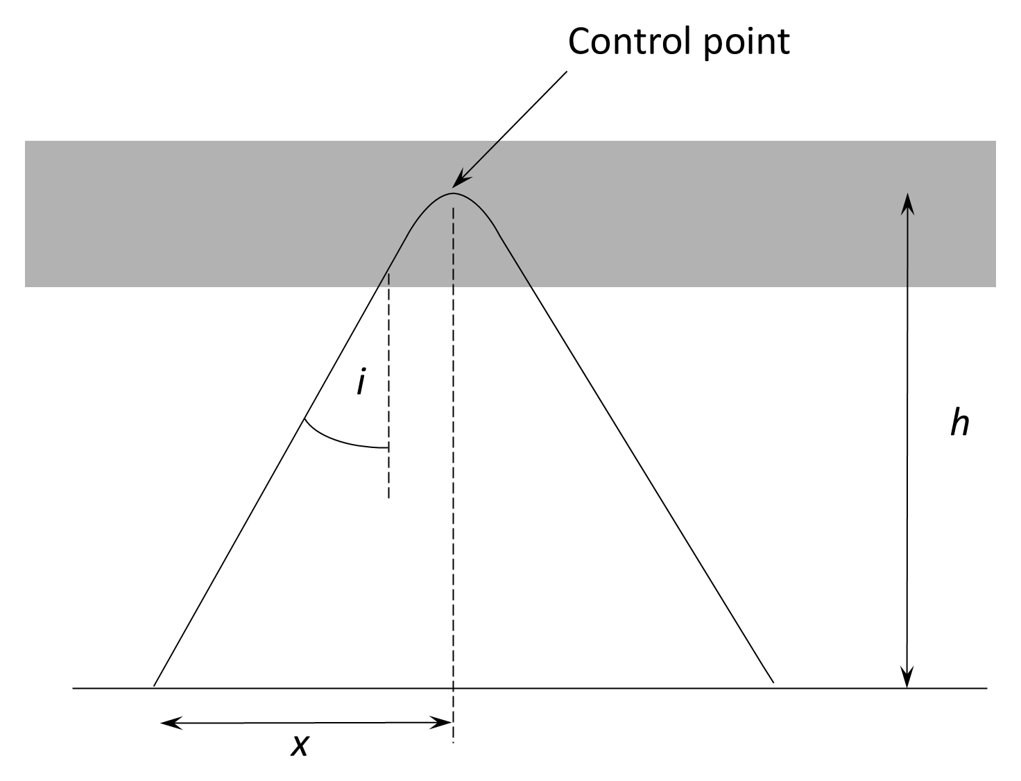
The MUF and the OWF can be obtained from the critical frequency, fo. To do this we need to know the path of our link to identify which portion of the ionosphere is responsible for the refraction of the wave. Obviously this is the mid-point of the path, which is called the control point for the link since it is this part of the ionosphere that will ‘control’ the performance of the link.
Using the trigonometric relationships of Figure 11.24:
The secant law arises from the increased path length through the ionosphere at oblique incidence.
Equation (11.53) holds up to about 1,000 km, after which the curvature of the Earth must be taken into account so that:
where ksec(i) is known as the MUF factor which is normally provided in a series of tables.
The value of i can be calculated using the horizontal distance x from the transmitter and receiver sites to the control point and h, the height of the refracting layer at that point so that:
The value of the OWF can then be calculated.
The calculation of the MUF therefore requires the user to calculate the critical frequency and height of the control point for a particular path. Fortunately, critical frequency and control point heights are being measured and predicted continuously around the world and information charts are produced that provide the OWF values for a large number of control points. Fixed links such as those used in strategic HF circuits will have constant control points and OWF predictions can be regularly produced.
Lowest usable frequency (LUF). The LUF is the lowest frequency that can be used for a given link. Below the LUF the noise and absorption in the path are too great. As we saw earlier, the LUF is normally dictated by the absorption and noise in the D layer and the LUF is sometimes known as the absorption-limiting frequency (ALF). Accurate prediction of the LUF is difficult due to variations in D-layer properties.
Fading. In sky-wave systems, it is often found that the received signal strength is the sum of two independently fading components that have travelled by paths with different propagation times. In such cases, the fading of the total received signal varies with frequency and the two components may cancel to give deep fading. Signals travelling through the ionosphere suffer from severe fading of two types:
- Fast fading (typical fade times of between 0.1s and 10s), which has two principal types of interference fading or polarization fading. Interference fading arises because the received signal is effectively the sum of many components, each having travelled by a different path. Polarization fading arises from magneto-ionic splitting in the ionosphere, whereby the Earth’s magnetic field divides the incident wave into two characteristic modes—the ordinary (O) and extraordinary (X) waves—which follow slightly different paths and experience different phase velocities before recombining at the receiver.
- Slow fading (fade times of minutes, hours, or even days) is normally the result of gradual changes in ionospheric conditions at the control point.