11.5.2 Communication By Sky Wave
In free space, radio waves travel in straight lines providing that the medium through which they pass has a constant density, and therefore a constant refractive index. In the ionosphere, the influence of the free electrons is such that ionosphere has a refractive index profile and the layers refract HF waves so that they follow a gradual curved path. Thus, as a wavefront enters the D layer, its velocity is reduced and a slight bending of the wavefront occurs. The D layer has very few free electrons, so only LF waves are readily absorbed.
HF waves are not refracted very much by the D layer and continue up to the E layer where, due to that layer’s greater number of free electrons, the wave begins to be refracted. If there are sufficient electrons, the path of the wavefront is refracted progressively until it is returned toward the Earth. As noted earlier, the electron density of the ionosphere changes continuously with height and has maxima at each layer. This variation is normally considered as a series of layers of constant variation; each layer successively refracting the wave until it is eventually returned to Earth.
As the transmission frequency is raised, the wave travels further into the layer before being refracted. Finally, a frequency will be found beyond which the waves will not be refracted sufficiently to curve their path back to Earth and they continue up to the next layer (or, in the case of the F2 layer, on out into space).
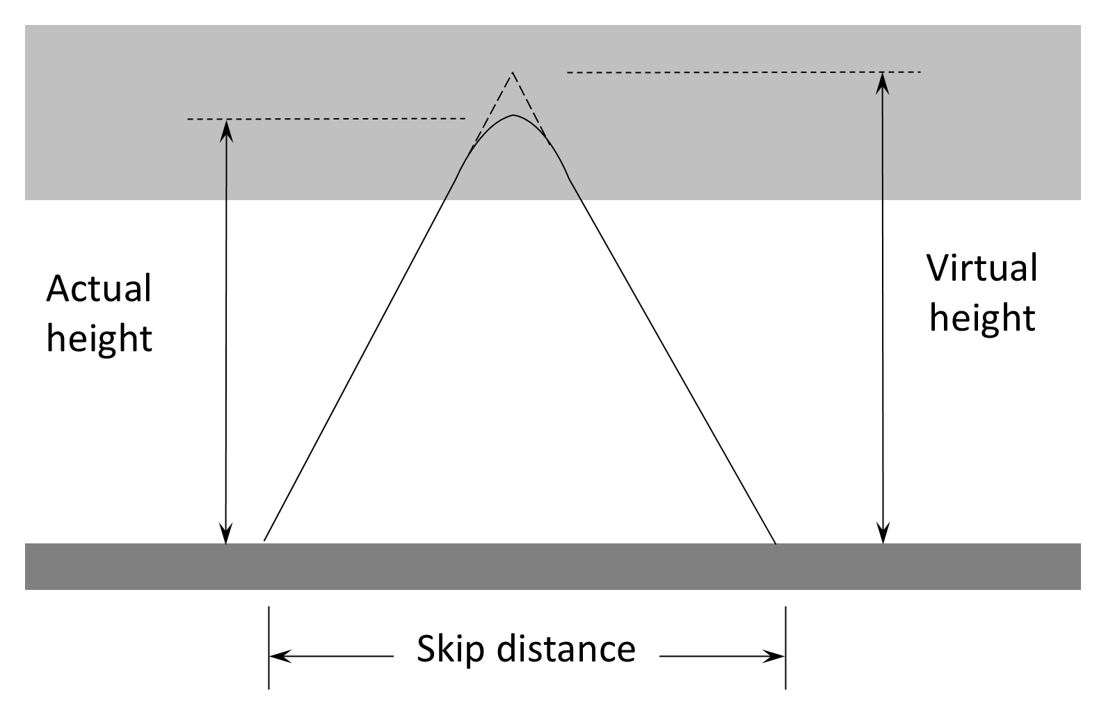
Figure 11.18 illustrates that the refraction process is often considered to be a reflection process with the actual height of the refractive ionosphere replaced by a hypothetical virtual height of the reflective ionosphere.
The range of sky-wave communications varies and is determined by three main factors: the frequency of operation, the angle of transmission, and the power of the transmitter.
11.5.2.1 Frequency Of Operation
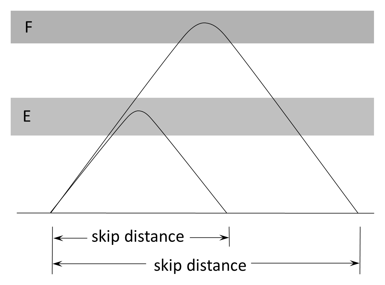
When the frequency is raised, the wave is refracted by a higher portion of the current layer, or by a higher layer. Figure 11.19 shows that this affects the range of communication since refraction from the E layer leads to a shorter range than that of the F layer. The distance between the transmitting antenna and where the first usable sky wave returns to Earth is called the skip distance.
11.5.2.2 Propagation Angle
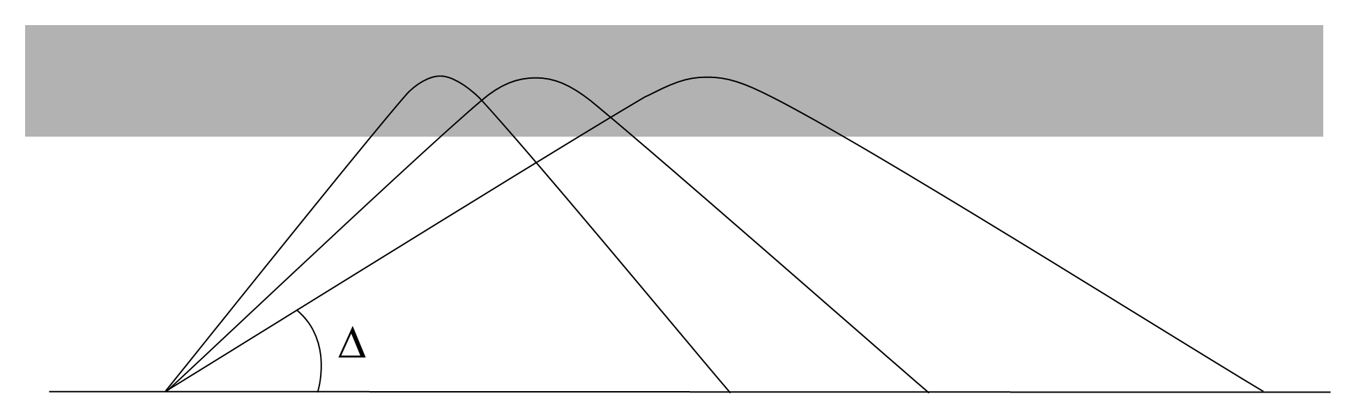
The propagation angle (also known as the take-off angle and sometimes as the angle of departure) of a sky-wave transmission (Δ) is the angle between the wave and the ground. As illustrated in Figure 11.20, if the propagation angle is lowered, a greater communication range is achieved. As a general heuristic, the maximum skip distance possible using the F2 layer at its summer height is approximately 3,500 km using a 5° propagation angle; using a propagation angle of approximately 80° using any layer leads to a skip distance of approximately 100-150 km.
A special case of propagation angle is when the angle is ninety degrees, that is, the wave is vertical. If the frequency of a vertically incident wave is increased, the wave penetrates higher before returning. Eventually the frequency would be such that a wave does not return. The highest frequency that returns to Earth from a vertical incidence transmission is called the critical frequency, called fcrit or, more commonly, fo. Since each layer has a critical frequency, further subscripts are often used to denote fo(E), fo(F1) or fo(F2).
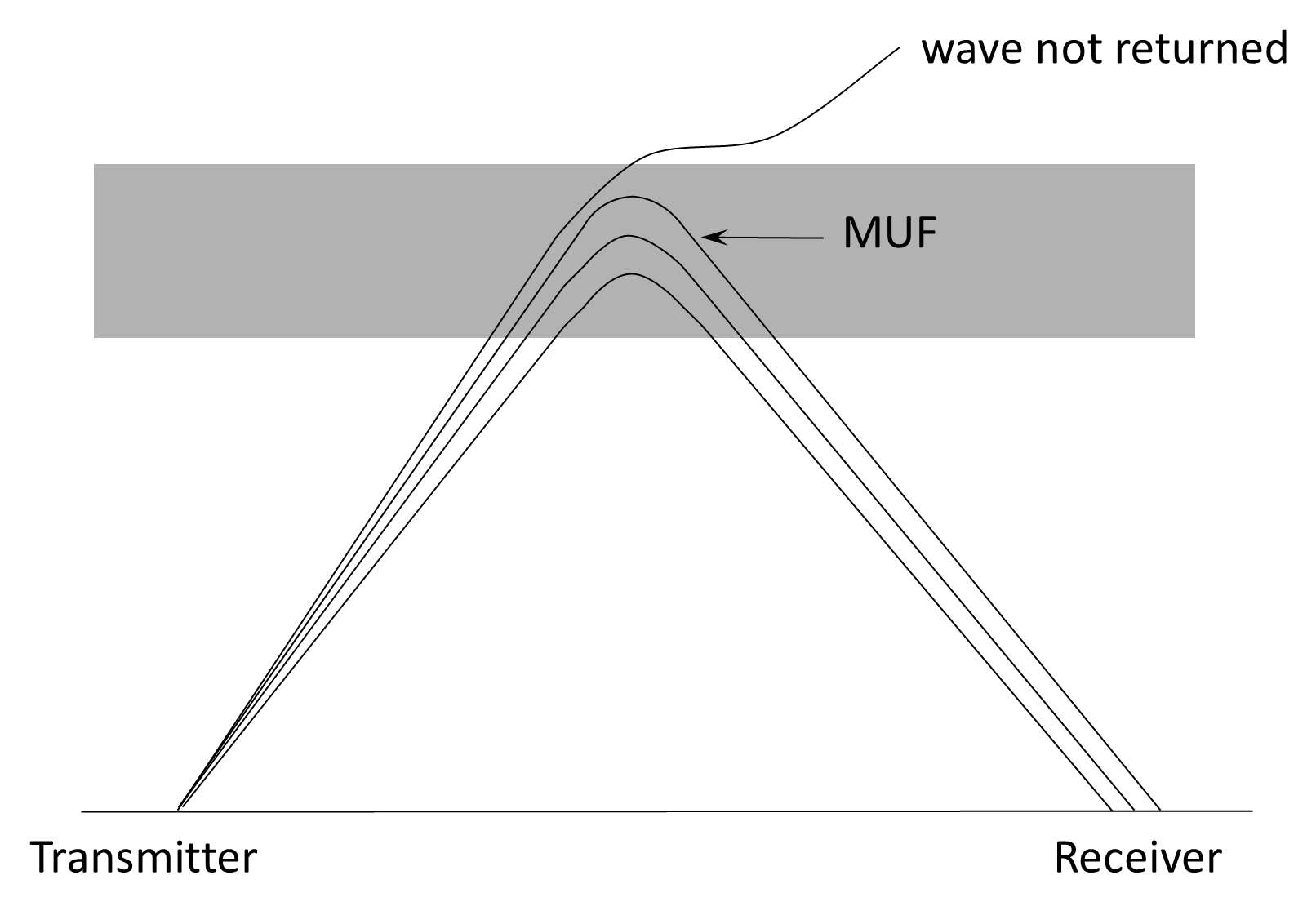
Figure 11.21 shows how increasing the operating frequency affects communication over a particular range. An increase in frequency requires an increase in propagation angle until the frequency exceeds the MUF and the wave is not returned to Earth.
11.5.2.3 Power
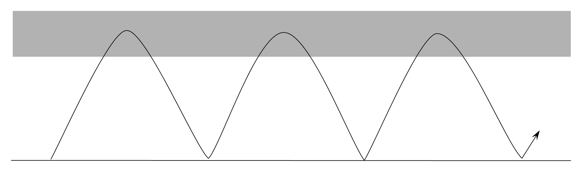
It is obvious from the preceding discussion that, for a given antenna, an increase in the range of HF communications is achieved by raising the frequency of operation. Increasing the power has no effect on communications range for a single hop. Using the highest frequency at the lowest possible propagation angle, a single-hop for HF sky wave is limited to approximately 3,500 km. Increasing the power of the transmission can have an effect on range, however, due to the occurrence of multiple hops of the transmission. As the wave is refracted back to Earth, it has sufficient power to be reflected back up to the ionosphere where it is again refracted, as illustrated in Figure 11.22 creating paths with longer ranges.
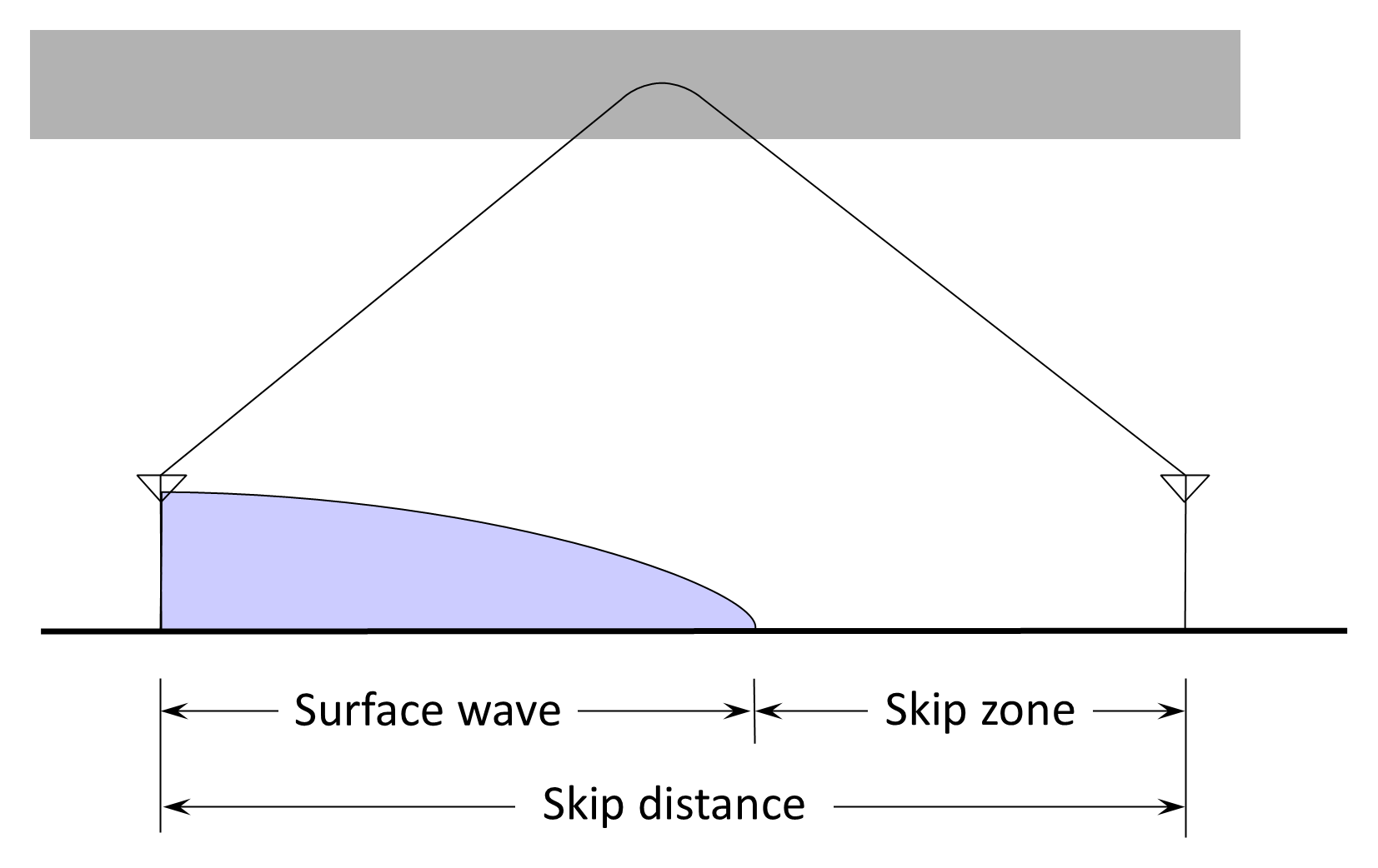
Skip zone. Communication is possible in the lower portions of the HF band in both the surface-wave and sky-wave modes. Because HF surface wave has limited range and there is a minimum value of skip distance for useable sky-wave communications, there often exists a region called the skip zone, quiet zone, or the dead zone. As illustrated in Figure 11.23, the skip zone is the area between the point where surface wave diminishes and where the first useable sky wave returns to Earth. Communication to stations in this region is not possible in the HF band. As a corollary, however, where there is a good conducting surface, such as over seawater, there may not be a skip zone and the receiving antenna may receive both surface and sky wave and the two signals will interfere with each other.