
11.3.5 Reflection Loss
The received signal is affected by ground reflections and contains two components as we saw earlier: the direct wave and the ground-reflected wave. Figure 11.10 illustrates these two components and the geometry of the radio link.
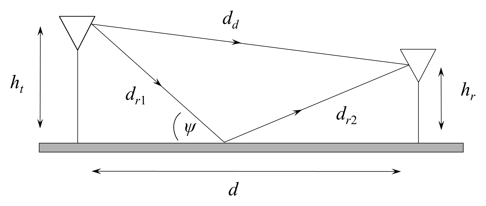
Energy striking the ground at a low angle is reflected. The exact amount of energy reflected depends on the type of ground; the flatter the ground, the more energy is reflected. For rough ground, waves of greater wavelength will be reflected with more energy than waves of a shorter wavelength. Horizontally polarized waves experience a phase change of 180° on reflection; the phase change for vertically polarized waves depends on the angle at which the wave strikes the ground. At the low angles found in radio path reflections the phase change is approximately 180°. Vertically polarized waves generally lose more energy at the point of reflection than horizontally polarized waves. The amount of energy lost is dictated by the reflection coefficient Ar.
Now we are interested in the total received signal strength, which is the sum of the direct and ground-reflected waves. The direct path (for d>>ht) is:
and the reflected path is:
by a binomial approximation. The path difference is therefore:
This path difference produces a phase lag of:
In that case, the field strength at the receiver (Er) is the sum of the free-space field strength (Eo) and the reflected field strength (ArEo) with the phase differences as illustrated in the phasor diagram of Figure 11.11.
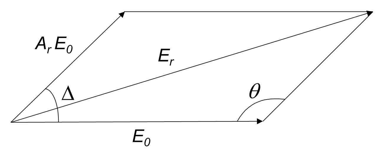
From Figure 11.11, applying the cosine rule to the angle θ = π − Δ:
For simplicity, the ground is generally assumed to be flat and to have a reflection coefficient of Ar=1 (that is, the wave is not attenuated and has a phase change of 180°), which is a sufficient approximation for both horizontal and vertical polarization at grazing angles for frequencies in the VHF and UHF ranges. As explained earlier, this is not true as some power will be lost due to absorption and scattering at the point of reflection. Still, with that approximation, Equation (11.32) becomes:
Since the total phase difference between the direct wave and the ground-reflected wave is Δ+π:
Using the identity :
Now the respective power densities are:
where ηo is the intrinsic impedance of free space (120π, or ~377 Ω).
Solving for received power density gives:
where Pden(o) is the power density of the direct wave.
So, we can see the effect of the ground reflection is for the received power density to vary between zero and 4Pden(o) in some periodic fashion.
If we convert Equation (11.38) to received power at the receiver terminals:
so that:
We saw the first part of this equation earlier in Equation (11.13) except that now we have accounted for reflection loss separately as noted in Equation (11.41).
Figure 11.12 shows the effect that reflection loss has on the free-space loss between two antennas separated by a distance d. When d is small, the phase difference at the receiver between the direct and reflected waves could rotate through several complete cycles bringing the two components in and out of phase several times. In this region, called the interference zone, large nulls occur. These nulls can be avoided by performing height/gain tests as the antennas are deployed.
The nulls arise when:
The last null occurs when dλ=4hthr, so that the interference zone is the region in which:
where ht and hr are the effective antenna heights above the reflecting plane. For an ideal flat path the effective antenna height is also the height above the local ground. For irregular paths, however, the ground cannot be considered as the reflecting plane, and empirical testing has shown that the reflecting plane can be obtained by finding the least-squares-fit straight line for the path profile when drawn on k=4/3 paper. For radio planning, the effective heights ht and hr are replaced by the modified heights hT and hR.
Equation (11.41) and Figure 11.12 show that the received signal strength passes through maxima and minima as the distance between antennas, or their height, is varied. Equation (11.41) shows that the theoretical maximum of the received field is twice the free-space field. Additionally, regardless of the height of the transmit antenna, the received signal strength is zero when hr is zero, that is at the surface of the Earth.
For a perfectly reflecting surface, the maxima of Figure 11.12 are larger and the minima tend to zero. The maxima and minima of Figure 11.12 are much softer in reality due to the imperfect reflection from the Earth’s surface.
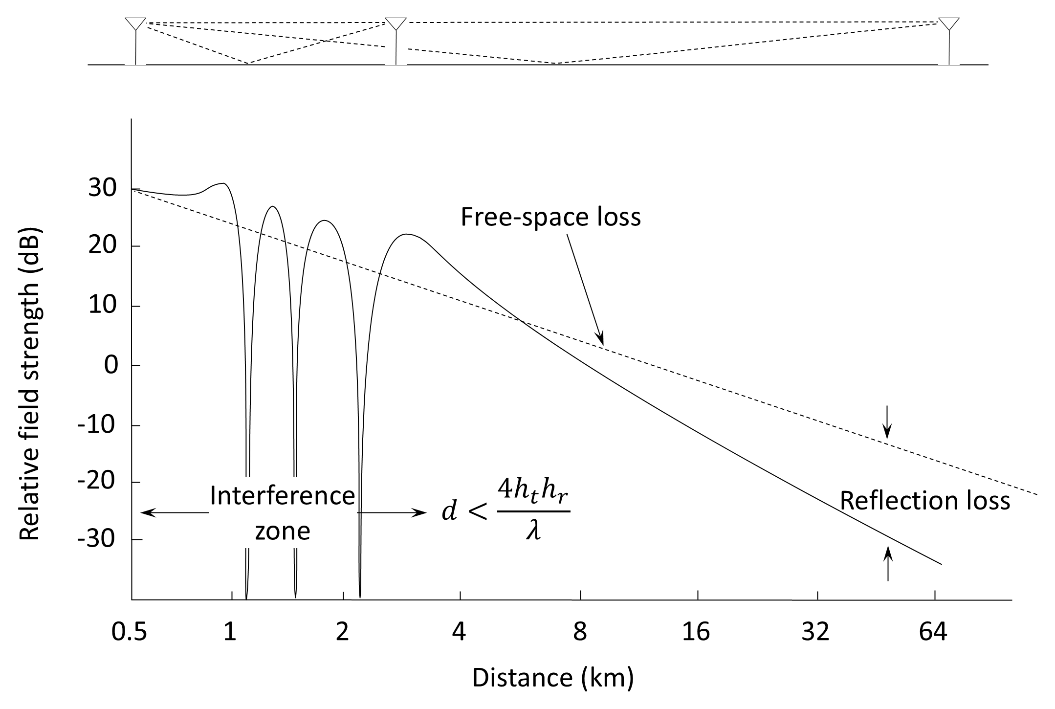
As the range between antennas is progressively increased (or the antenna height reduced) the path difference between the direct and the reflected wave becomes smaller and this, together with the 180° phase change at the reflection point, causes the reflected energy to become progressively more out of phase with the direct energy (in theory, completely out of phase at infinite range). Thus, there would be a steady reduction of signal strength caused by reflection loss as shown in Figure 11.12.
In practice, reflections are not perfect and the reflection point is not regular. Imperfect reflections and irregular terrain cause less loss than predicted by Equation (11.40) and performance predictions for different types of terrain are based on results that have been derived empirically.
11.3.5.1 Plane Earth Loss Formula
At large distances the term Δ becomes small as d becomes large compared to the antenna heights:
Therefore, since sin(x) ≈ x for small arguments, Equation (11.40) becomes:
Equation (11.47) is identical in structure to Equation (11.13) except that FSL is replaced by the quantity (hthr/d2)2 which is often referred to as the plane-earth loss (PEL). Note that Equation (11.47) shows that the received power at a large distance is independent of wavelength. Note also that the plane-earth model implies the inverse fourth law with respect to distance. Doubling the path length reduces the received signal by 12 dB (by 16 times), four times as much as for free-space conditions.
Back to reading