
3.2.3 PCM
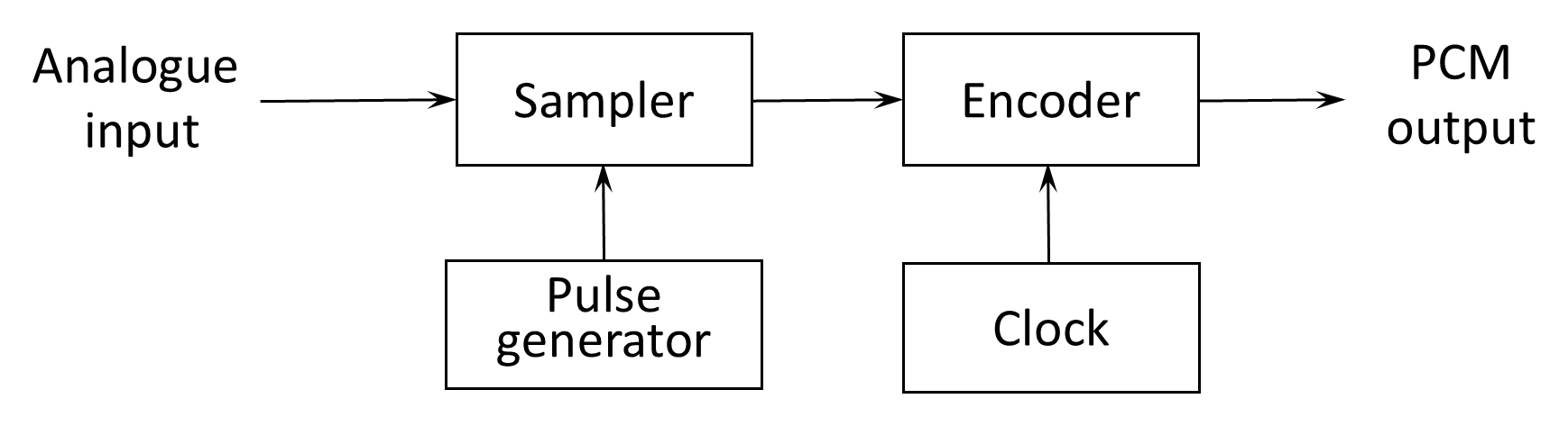
In PCM, the information conveyed is independent of the precise pulse shape, and small variations in pulse timing are not critical. The analog signal is first sampled to form a sequence of pulse-amplitude modulation (PAM) samples, which are then encoded into a binary code and transmitted as a digital bitstream. At the receiver, the binary codes are decoded to recreate the PAM samples, which are subsequently filtered to reconstruct the analog waveform. Figure 3.4 shows the block diagram of a PCM system. Figure 3.6 shows the block diagram of a PCM converter.
The encoder converts a sequence of analog voltage samples into a binary representation. To understand this process, it is useful to briefly review binary representation (a more detailed discussion of binary numbers is provided in Appendix E). Figure 3.5 illustrates how voltage levels from 0 V to 7 V may be represented using three-bit binary numbers. With three bits, a total of 23=8 distinct amplitude levels can be represented. If four bits are used 24=16 levels become available, and so on. In general, each additional bit doubles the number of representable levels and improves the resolution of the digital representation.
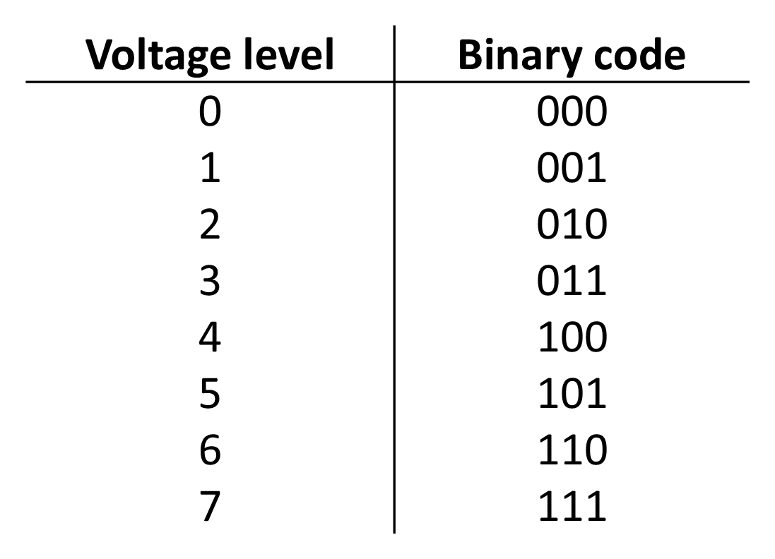
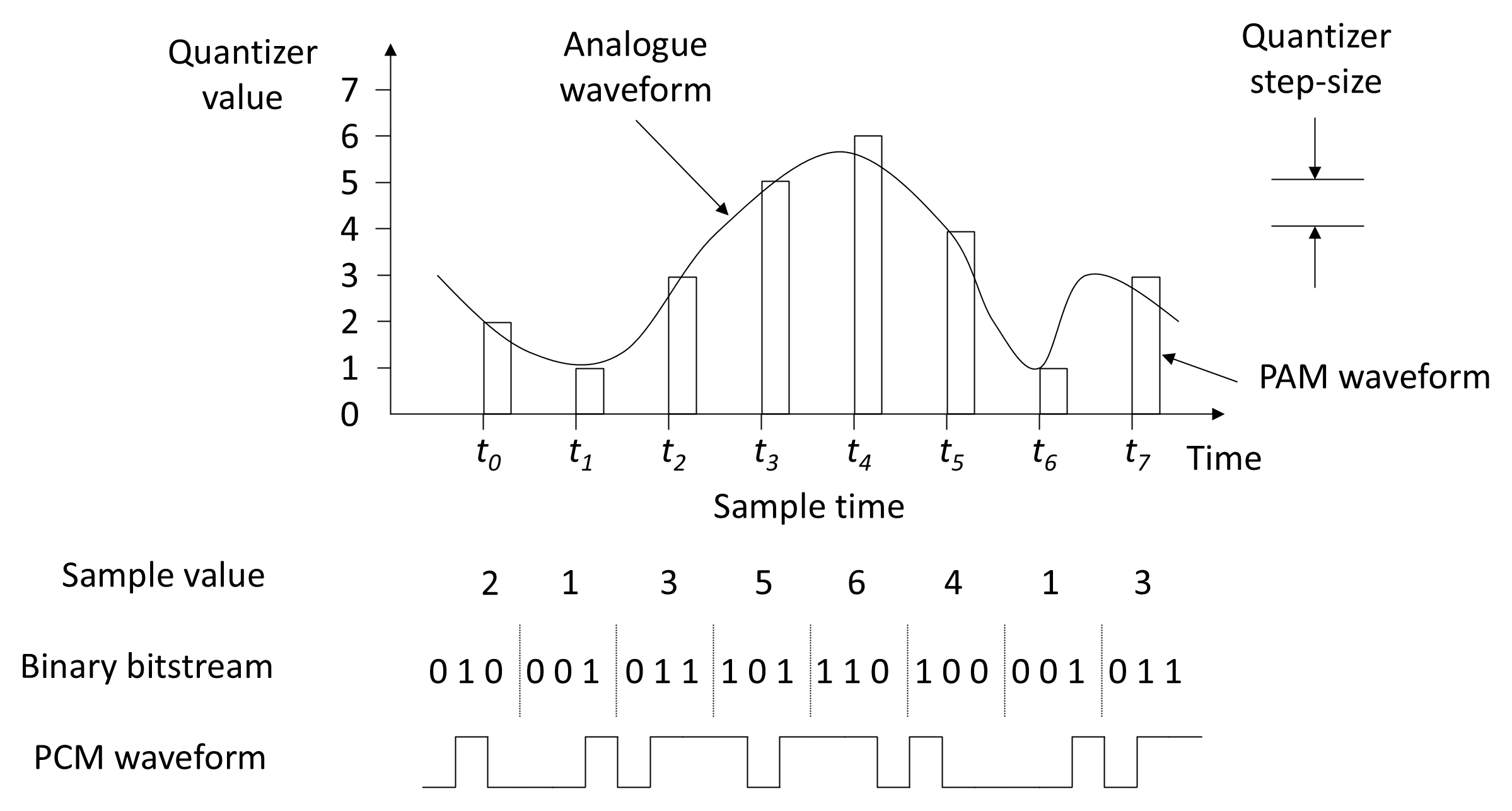
Figure 3.6 illustrates the waveforms generated in a PCM system. At time t0 the analog signal has a voltage of 2 V corresponding to the closest binary code 010. At time t1 the analog signal amplitude is approximately 1.15 V, but with only eight available quantization levels, the nearest representable value is 1 V, encoded as 001. When the signal is reconstructed at the receiver, the recovered value therefore differs from the original by 0.15 V. The process of mapping a continuous range of amplitudes onto a finite set of discrete levels is known as quantization (from the Latin root quantus meaning ‘how many’—the English word quantum has the same root and is used to describe a discrete quantity). The resulting discrepancy between the original and reconstructed signals is referred to as quantization error or quantization noise. From Figure 3.6 it can be seen that the largest error that can occur is equal to half the quantize step-size. The maximum quantization error in a uniform quantizer is equal to half the quantization step size. Increasing the number of quantization levels reduces the step size and therefore reduces the quantization error. Each additional bit halves the step size and improves the resolution of the digitized signal.
3.2.3.1 Example — Digitized Voice
To transmit digitized voice, we know that the useful speech bandwidth extends to approximately 3.4 kHz. According to the Nyquist criterion, the signal must therefore be sampled at a rate of at least 2 × 3.4 kHz = 6.8 kHz. In practice, a standard sampling rate of 8 kHz (8,000 samples per second) is used in telephony systems.
If an 8-bit encoder is used (providing 28=256 quantization levels), the resulting bit rate is:
This 64 kbps rate is the standard for a single digital voice channel in systems such as PCM telephony and T1/E1 transmission links (see Chapter 7).
3.2.3.2 Quantization Noise
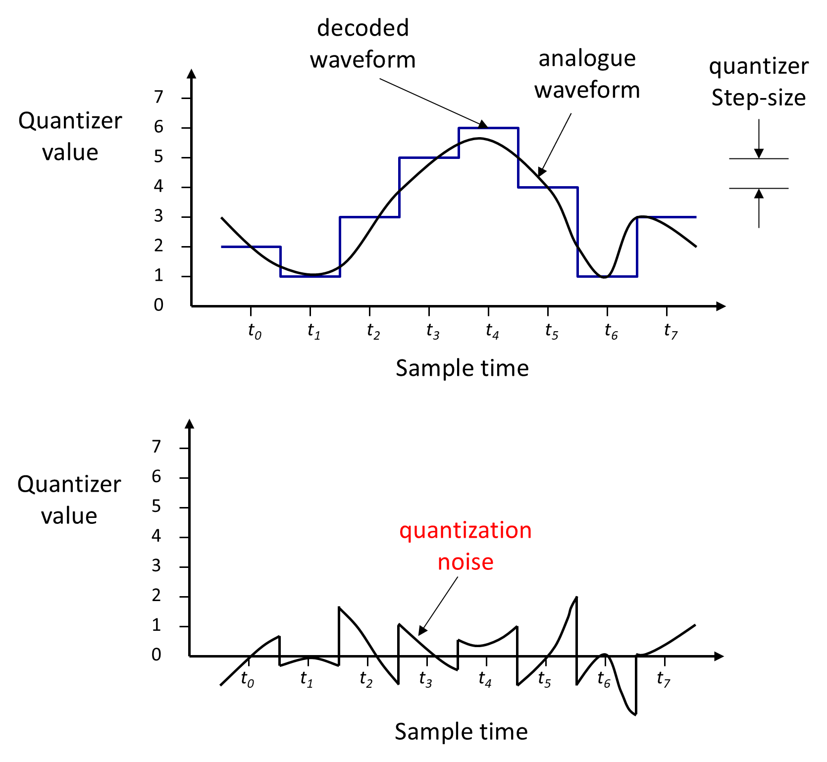
Quantization noise is the difference between the decoded PCM waveform and the original analog waveform, as illustrated in Figure 3.7. Increasing the number of quantization levels reduces this error and improves signal fidelity.
The signal-to-quantization-noise ratio (SQNR) provides a useful measure of quantization performance. For a uniform quantizer with 2n levels, the SQNR (in decibels) is approximately:
where n is the number of bits per sample. This shows that each additional bit improves the SQNR by about 6 dB, corresponding to a doubling of resolution.
3.2.3.3 Companding
In a PCM system employing uniform quantization, the quantization step size is constant across the full dynamic range of the signal. As a result, the absolute level of quantization noise is the same for both weak and strong signals. This leads to a relatively poor signal-to-noise ratio (SNR) for low-amplitude signals, which is undesirable for speech, where much of the signal energy is concentrated at low levels.
This limitation is addressed using nonlinear quantization, implemented through companding—a process in which the signal’s dynamic range is compressed prior to quantization and expanded after decoding. Companding allocates finer quantization steps to low-level signals and coarser steps to high-level signals, producing a more nearly uniform SNR over the signal’s dynamic range.
Two standard companding laws are widely used in telecommunication systems. North American systems use the μ-law (μ=255):
while European networks use the A-law (A=87.6):
where x and y are the normalized input and output voltages respectively.
3.2.3.4 Differential And Adaptive Differential PCM
While companding improves coding efficiency in the amplitude domain, further reductions in bit rate can be achieved by exploiting temporal redundancy in the sampled signal. In DPCM, the encoder transmits the difference between successive samples rather than their absolute values. Because adjacent speech samples are typically highly correlated, these difference signals have a smaller dynamic range than the original waveform and can therefore be quantized using fewer bits per sample.
Although DPCM requires a significantly lower bit rate than conventional PCM, it is still affected by quantization noise and may suffer from slope overload distortion when the signal changes rapidly (see Section 3.2.4). A widely used standardized form of DPCM for voice telephony is the 32 kbps scheme adopted by ITU-T in Recommendation G.726.
In practice, the statistical properties of the difference signal are not stationary and can vary considerably over time, particularly during rapid transitions in speech. Adaptive differential PCM (ADPCM) addresses this limitation by employing an adaptive quantizer whose step size is continuously adjusted to track the short-term characteristics of the signal. This adaptation improves coding efficiency while reducing the likelihood of overload distortion.
ADPCM remains a waveform coding technique—it does not rely on an explicit speech production model—but it achieves substantial bit-rate reductions relative to conventional PCM while maintaining acceptable speech quality. Standardized ADPCM systems operate at fixed rates such as 32 kbps, as well as at lower rates (for example 24 kbps) with some reduction in quality. In practice, the subjective speech quality of 32 kbps ADPCM is comparable to that of 64 kbps PCM.
The ITU-T G.721 recommendation specifies a transcoding algorithm in which the encoder accepts an A-law or μ-law PCM bitstream as input and converts it to an ADPCM representation. At the receiver, the corresponding decoder reconstructs the signal and outputs a PCM bitstream compatible with standard telephony systems.
Back to reading