
7.3 TDM
TDM achieves transmission efficiency by allowing multiple information channels to share a common medium through time interleaving rather than frequency separation. By allocating the full channel bandwidth to each user for a short, recurring time interval, TDM is particularly well suited to digital signals and forms the foundation of most modern digital transmission systems.
A typical TDM system is illustrated by the block diagram of Figure 7.9. The transmission subsystem may use any form of pulse modulation, with the modems between the pulse modulators and the transmission channel typically based on FSK or PSK.
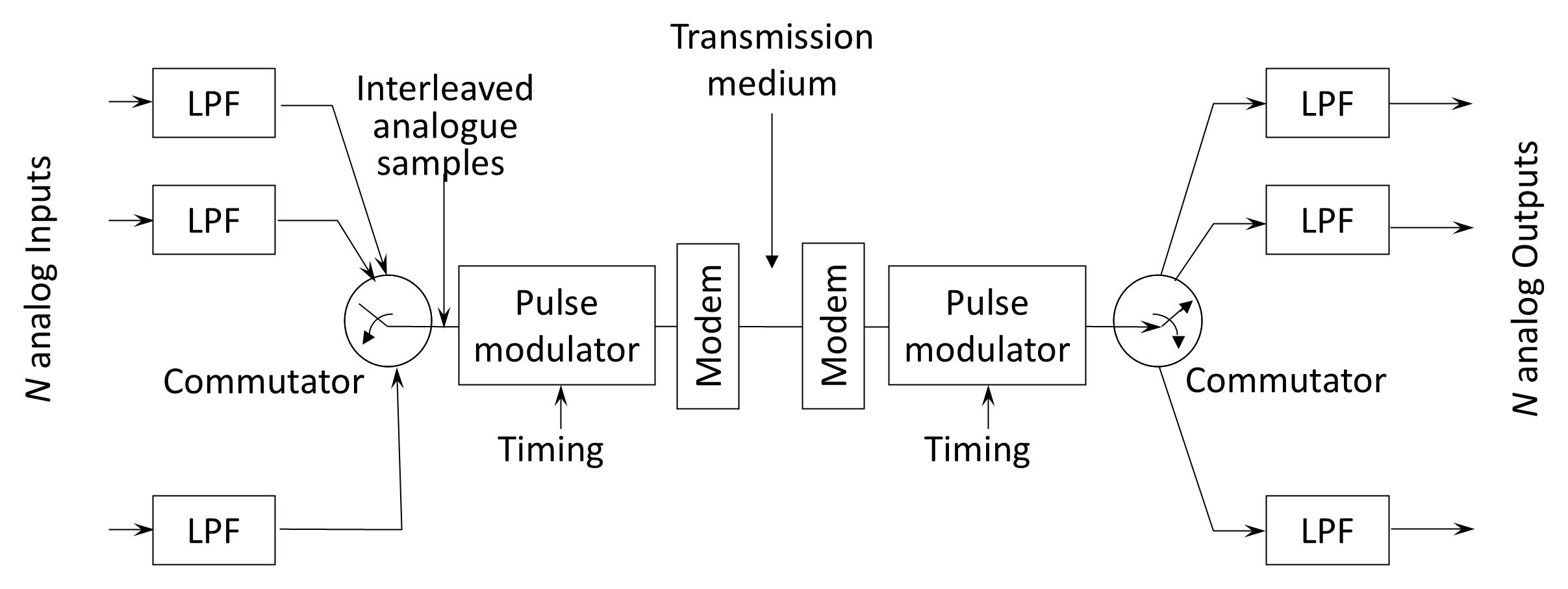
As in all pulse-modulation systems, the first operation in TDM is sampling or digitization. Sampling in a TDM system is performed by the input commutator, which sequentially samples all N in input channels once per revolution. Thus, each channel is sampled once during each sampling period T, or at a rate of fc = 1/T samples per second.
As with FDM systems, the input channels of a TDM system must be band-limited to prevent distortion due to aliasing. Each input waveform passes through a low-pass filter, constraining its spectrum below a maximum frequency fm. Consequently, the sampling rate must satisfy the Nyquist criterion:
This sampling rate corresponds to the bit rate required to transmit each signal separately, assuming a pulse modulation scheme that allocates one bit per sample. Because the minimum bandwidth required to transmit a digital waveform is one-half of the bit rate, the minimum bandwidth B0 for a single-channel system is:
If a pulse modulation technique transmits M pulses per sample, the bandwidth expands by a factor of M:
In practical systems, additional bandwidth is required for pulse shaping and guard intervals.
Following commutation, the multiplexed analog samples are presented to the pulse modulator, where each sample is converted into a series of digital pulses and transmitted. Since the pulses from N single-channel inputs are interleaved, the overall channel bandwidth must be N times that of a single input channel:
The input commutator therefore has two principal functions: to take a narrow sample of each of the input waveforms; and to interleave (time-division multiplex) these N samples.
At the TDM receiver, the narrow pulse samples are regenerated and distributed by the output commutator, which operates synchronously with the input commutator. Each pulse is directed to its corresponding channel filter, and a final low-pass filter reconstructs each of the N channel waveforms.
Figure 7.10 illustrates the timing of a digital TDM system. A major advantage of TDM over FDM is its direct compatibility with digital input signals—when the inputs are already digital, the commutator simply interleaves existing data words rather than sampling analog waveforms.
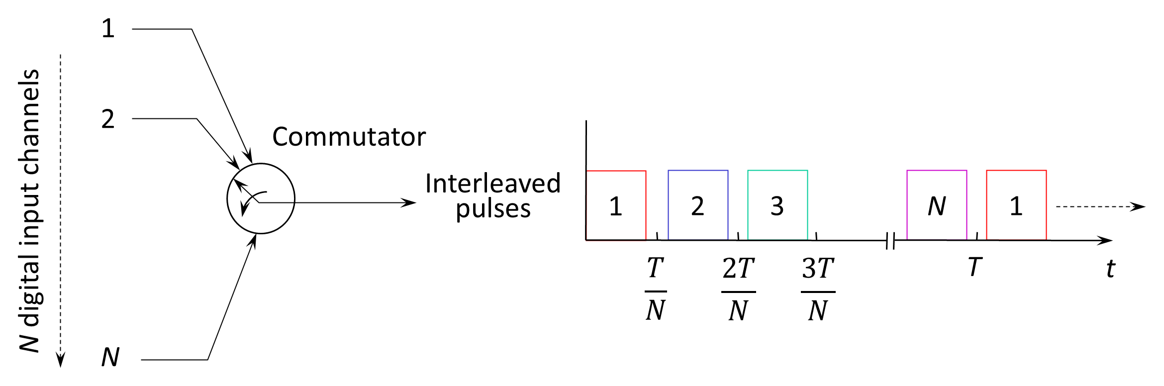
As shown in Figure 7.10, one of the advantages of TDM over FDM is its direct application to digital signal inputs. In this case the commutator does not need to sample but simply interleaves the incoming pulse samples.
Back to reading