
7.2 FDM
The most common means of implementing FDM is by using the minimum-bandwidth properties of single-sideband (SSB) modulation. Because SSB suppresses one sideband and the carrier, it reduces required bandwidth to approximately the message bandwidth. This approach allows multiple channels to be combined efficiently within the smallest possible bandwidth. The block diagram of a typical FDM transmitting system is shown in Figure 7.1.
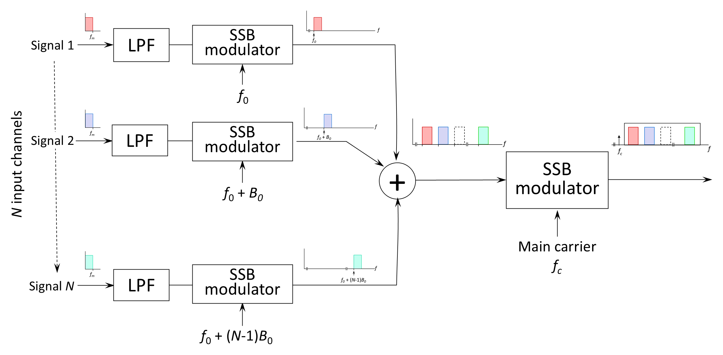
Each input information channel is band-limited to a maximum frequency, fm, assumed equal for all channels. Band-limiting is necessary to prevent crosstalk arising from overlapping spectra of adjacent channels and to simplify channel separation at the receiver. Each channel waveform is then modulated onto a sinusoidal subcarrier at the proper frequency, translating the channel to its allocated position in frequency.
To prevent interference, subcarrier frequencies must be closely controlled—typically by deriving all subcarriers from a master oscillator. Vacant frequency intervals, called guard bands, are inserted between channels to further reduce crosstalk and ease filter requirements during demultiplexing.
For SSB modulation, each channel occupies an overall bandwidth of:
where fm is the information bandwidth and Bg is the guard-band width.
For an FDM system comprising N channels, the total transmission bandwidth is therefore:
In practical systems, additional bandwidth is required for pulse shaping and guard intervals.
The composite FDM signal may then be modulated onto a main carrier using SSB, depending on system design and transmission medium. Figure 7.2 shows the spectral relationships for the system.
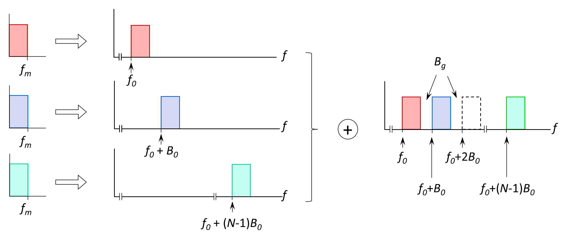
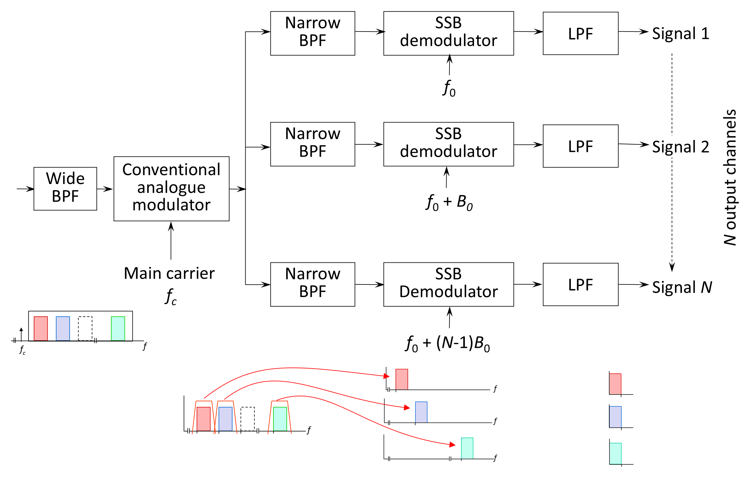
Figure 7.3 illustrates the block diagram of an FDM receiving system. At the receiver, the carrier is demodulated and each channel of the multiplexed group individually separated out by channel filters of bandwidth fm located at the sub-carrier frequencies. Typically, when SSB is used to form the multiplexed group, the channel filter outputs are individually SSB demodulated with sub-carriers of appropriate frequency to receive the original waveforms.
There are two groups of standards for FDM. The AT&T system is used in North America, while the ITU system tends to be used elsewhere. The ITU recommends that individual speech channels are transmitted in combinations of 12-channel groups, using the channel carrier frequencies and bandwidths of Figure 7.4.
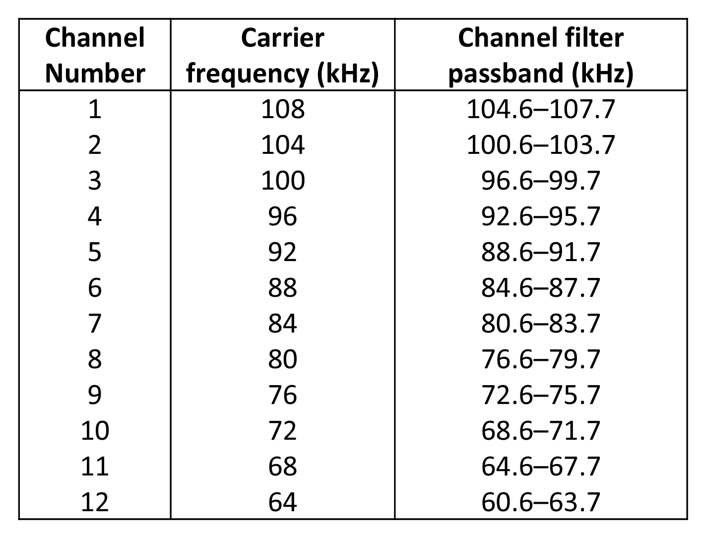
It should be noted that the bandwidths correspond to an audio bandwidth of 300–3,400 Hz. The transmitted bandwidth of the 12-channel group is therefore 60.6–107.7 kHz or approximately 60–108 kHz. The 12 channels are combined as illustrated in Figure 7.1. This combination is normally represented by the arrangement illustrated in Figure 7.5.
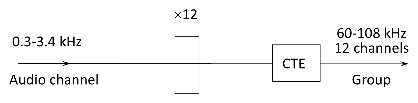
The channel translating equipment (CTE) incorporates 12 SSB modulators and is required to translate each channel in frequency to be combined into the group. Although the 12-channel group can be used for transmission in its own right, it is more commonly used as a building block for the next larger assembly stage. Five 12-channel groups can be combined to form a 60-channel supergroup as illustrated in Figure 7.6.

The group translating equipment (GTE) modulates each of the five groups using carrier frequencies of 420, 468, 516, 564, and 612 kHz. Group 1 occupies the band 60–108 kHz and is used to modulate the 420-kHz carrier producing a lower sideband of 420–(60 to 108) kHz or from 312–360 kHz, and so on for all five groups. Since each group has a bandwidth of 48 kHz, the bandwidth of the supergroup is 312–552 kHz or 240 kHz.
The next level of assembly is the hypergroup which is illustrated in Figure 7.7 where the block STE is the supergroup translating equipment. A hypergroup is formed by assembling 15 supergroups.

A hypergroup can be transmitted to line by itself as a 900-channel system or it may be combined with other hypergroups to produce a system with even larger capacity.
An alternative method of combining supergroups is used in some countries where five supergroups are assembled to form a 300-channel mastergroup. The five supergroups modulate, respectively, carrier frequencies of 1,364, 1,612, 1,860, 2,108 and 2,356 kHz. The mastergroup can be transmitted to line or combined with two other mastergroups to form a 900-channel supermastergroup.
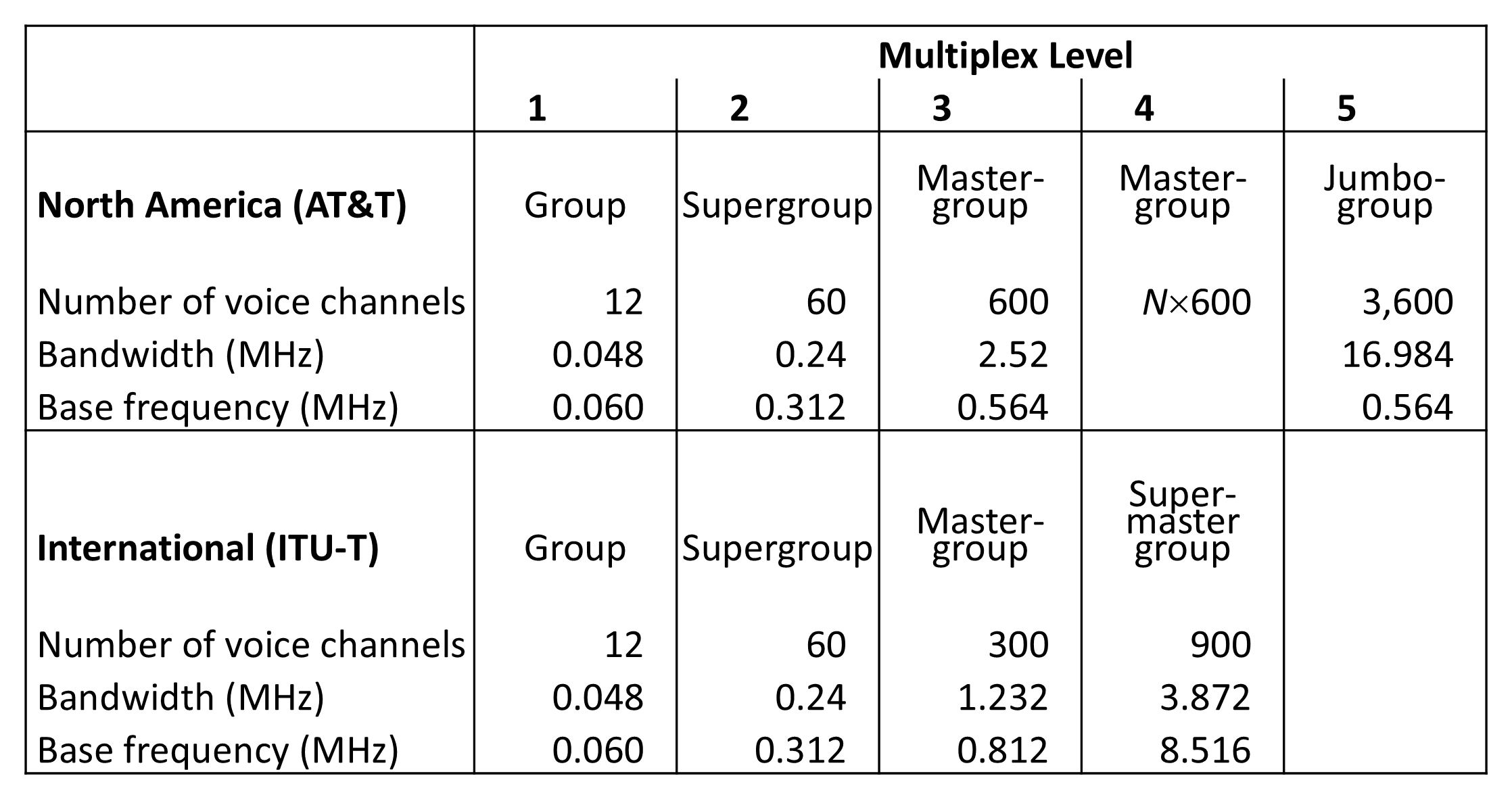
A comparison of the ITU and AT&T hierarchy of FDM is shown in Figure 7.8. The group and supergroup levels of the two systems provide the same numbers of multiplexed channels, with differing numbers at higher levels.
Although FDM formed the backbone of early analog carrier telephony, its complexity and limited scalability made it progressively less attractive as digital transmission and high-capacity links became widespread, motivating the transition to time-division multiplexing.
Back to reading