
7.3.3 PCM-Based TDM Hierarchies (E-Carrier And T-Carrier Systems)
The most widely deployed TDM systems are based on pulse-code modulation and standardized framing structures, which define how individual voice or data channels are assembled into higher-rate digital streams.
The European standard (E1) for PCM TDM (often referred to as the Conference for European Postal and Telegraphy PCM-30, or CEPT PCM-30) uses 30 voice channels at a total rate of 2.048 Mbps. Sampling occurs at 8 kHz, supporting a maximum audio frequency of 3.4 kHz. Each sample is quantized into 256 levels (8 bits), producing 8-bit codewords. Since each bit occupies 1/2,048,000=0.488 μs, each 8-bit sample lasts 8×0.488 or 3.9 μs. With a sampling period of 125 μs , the remaining time is used to carry additional PCM samples via interleaving, allowing for 32 channels per frame.
Although the E1 frame has 32 timeslots, only 30 carry user data. The remaining two are used for frame synchronization (timeslot 0) and signaling (timeslot 16), as illustrated in Figure 7.11.
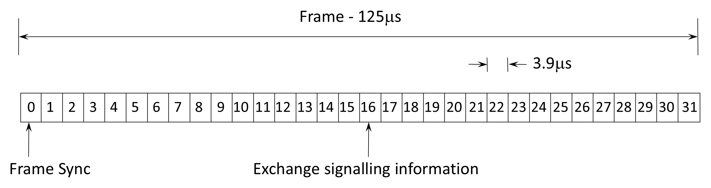
The European 30-channel E1 PCM system can be used as the basic building block for higher-order TDM systems, similar to the way in which large-capacity FDM systems are built up from the 12-channel group. The 30-channel frame consists of 32×8=256 bits so that the line rate is 256 bits/frame × 8,000 frames /second = 2,048 kbps. The higher-order bit rates are:
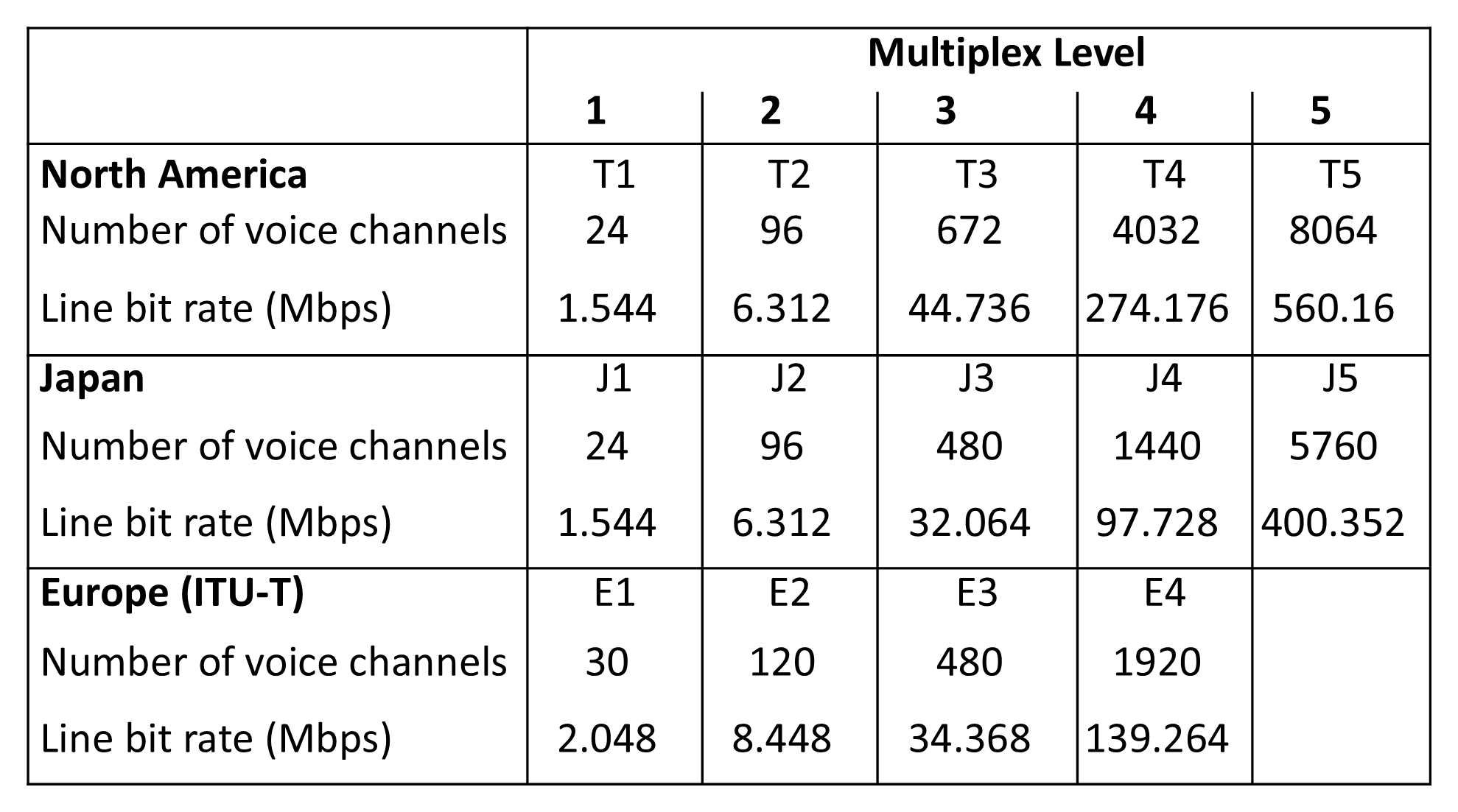
- 2nd order (E2) 8,448 kbps.
- 3rd order (E3) 34,368 kbps.
- 4th order (E4) 139,264 kbps.
Note, for example, that the group of four E1 channels in E2 has a higher data rate than just four times the E1 data rate. 4 × 2,048 = 8,192 (not 8,448) kbps. The surplus bits are used for synchronization and supervisory signals.
The North American (T1) system is structurally similar to E1 but differs in frame organization. Sampling occurs every 125-μs, producing 8-bit PCM words. A T1 frame contains 25 timeslots (0–24), but only 24 carry user data. There is no dedicated signaling timeslot or a synchronization timeslot—slot 0 contains a single bit for synchronization (frame alignment); the least-significant bit (the eight bit) of each sixth timeslot is used for signaling. Each frame contains 1+(8×24)=193 bits. With 8,000 frames per second, this yields a T1 data rate of 1.544 Mbps—the DS-1 rate when used for digital data. The higher-order bit rates are in Figure 7.12, which compares TDM systems used in Europe, North America, and Japan.
The TDM hierarchies described above were developed primarily for electrical transmission over copper and microwave links and are classified as plesiochronous systems, meaning that individual multiplexed streams operate at nominally identical but not perfectly synchronized clock rates. The resultant higher-order multiplexing rates are called plesiochronous digital hierarchy (PDH).
Back to reading