2.3.2 Spectral Content, Bandwidth, And Inter-Symbol Interference
As illustrated in Figure 2.25, a random polar NRZ bitstream composed of rectangular pulses has a power spectral density with a (sinx/x)2, or sinc2x, shape. This spectrum is obtained by taking the Fourier transform of a rectangular baseband pulse of duration Tb duration and is given by:
where f is frequency and Eb is the energy per bit. For a random polar NRZ sequence, the continuous power spectral density envelope of the bitstream is identical to that of a single rectangular pulse; the distinction lies in interpretation, with the former representing average power per unit bandwidth rather than pulse energy.
This spectrum illustrated in Figure 2.25 contains non-zero energy at arbitrarily high frequencies. In theory, therefore, a perfectly rectangular digital waveform requires infinite bandwidth. In practice, of course, all communication channels have finite bandwidth, and some degree of spectral truncation is unavoidable.
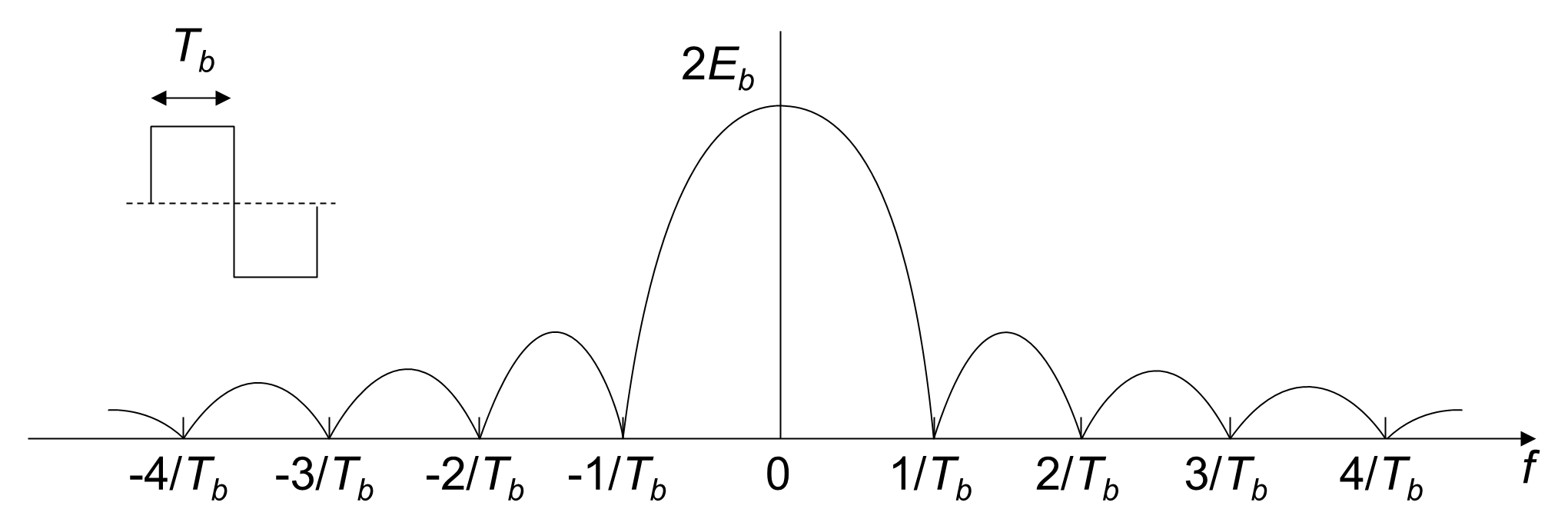
Figure 2.26 and Figure 2.27 illustrate the effect of bit rate on spectral occupancy for rectangular polar NRZ signaling (see Appendix D). Figure 2.26 shows the power spectral density of a 2 bps random bitstream. The spectrum exhibits nulls at even harmonic frequencies and lobes centered at the odd harmonics; the first lobe is centered at 1 Hz and the first null occurs at 2 Hz. When the bit rate is doubled to 4 bps, as shown in Figure 2.27, the spectrum expands proportionally such that the first lobe is centered at 2 Hz and the first null moves to 4 Hz. Although only a finite frequency range is shown in the figures, the spectrum theoretically extends to infinite frequency in both cases.
At the other extreme, it is common in introductory analysis to define the minimum practical bandwidth of a rectangular digital signal as half the width of the first spectral lobe. Under this approximation, the minimum bandwidth (in hertz) is equal to one-half of the bit rate (in bits per second). This definition provides a useful intuitive reference but does not represent a fundamental limit.
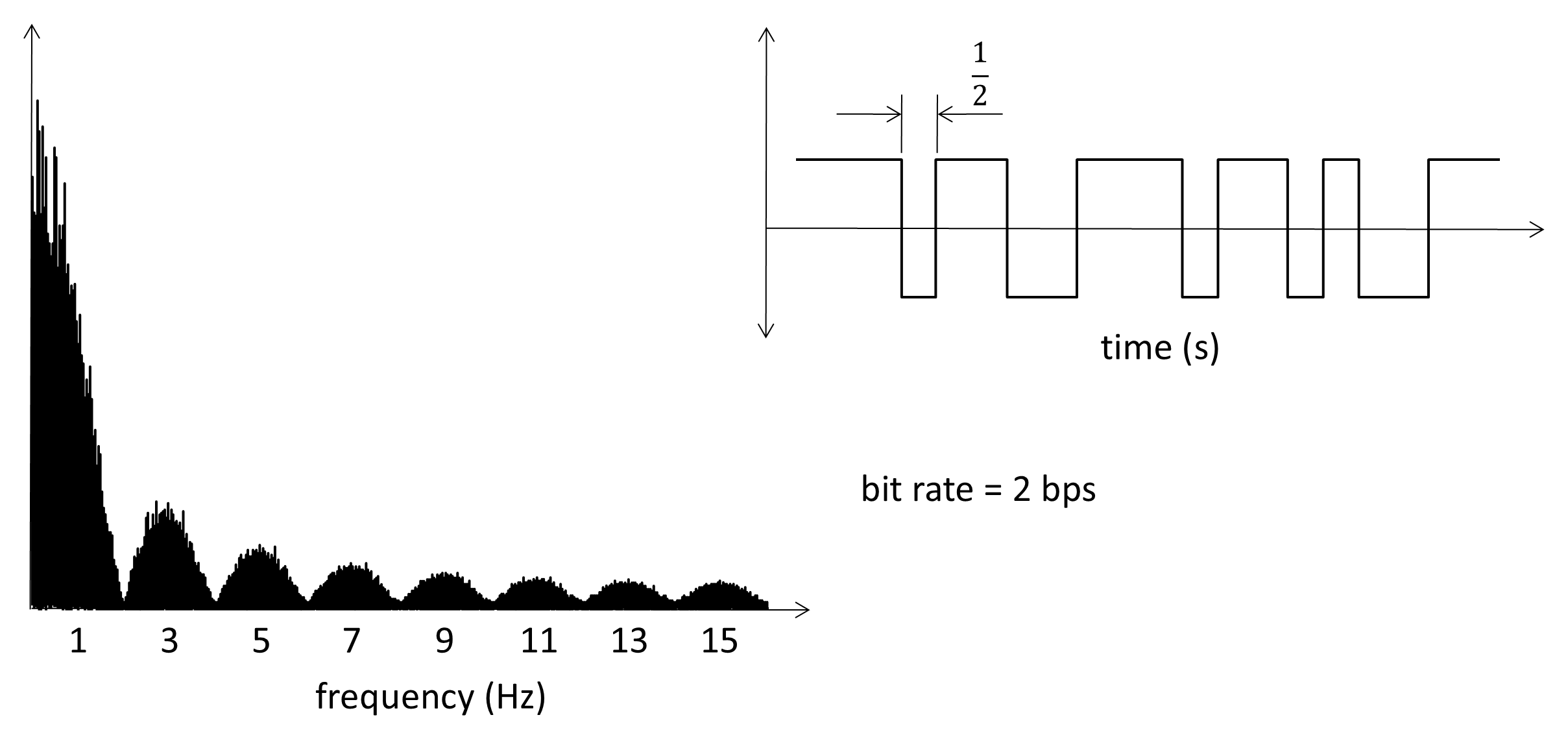
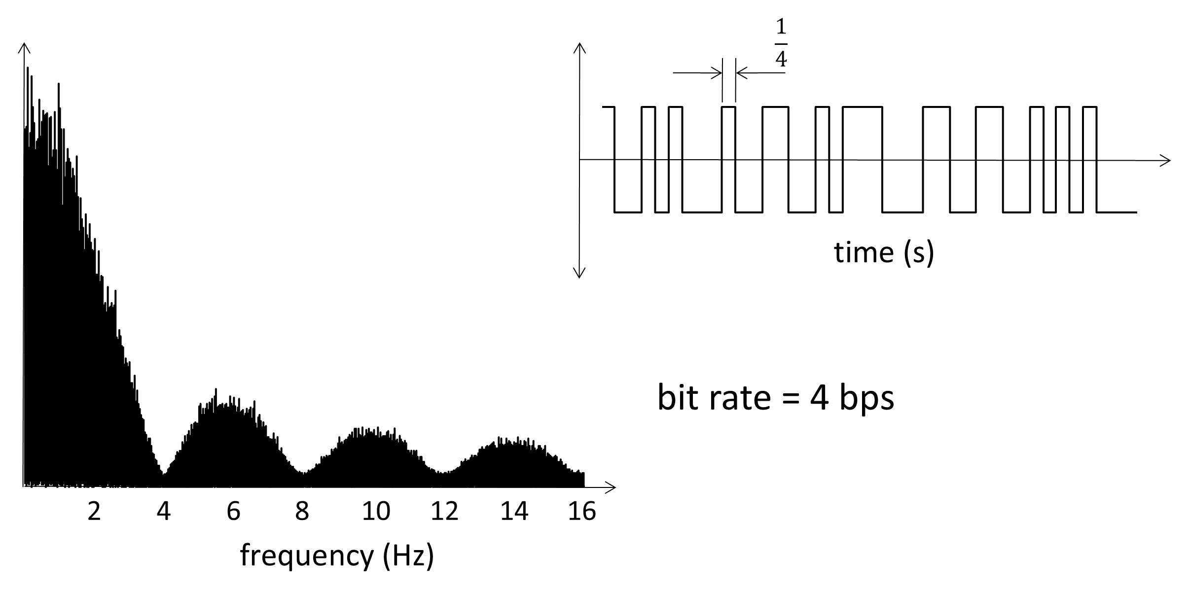
Figure 2.28 illustrates the consequence of truncating the spectrum of the 4 bps signal in Figure 2.27 to this minimum bandwidth of 2 Hz. The digital waveform originally transmitted is shown in black in the time domain, while the reconstructed waveform at the receiver is shown in red. The distortion introduced by the finite channel bandwidth causes symbols to be distorted and adjacent symbols to interfere with one another, an effect known as inter-symbol interference (ISI).
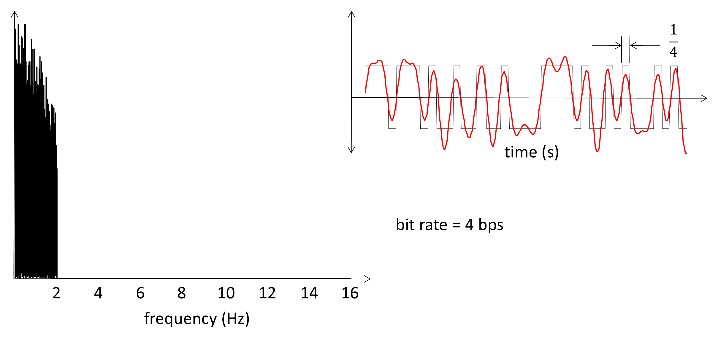
Whether imposed deliberately by filters or inherently by the physical transmission medium, this bandwidth limitation attenuates the high-frequency components of the digital waveform. As a result, sharp pulse edges are smoothed and the time-domain pulse spreads beyond its nominal symbol interval. ISI is therefore an inevitable consequence of bandwidth limitation and motivates the use of bandwidth-efficient pulse-shaping techniques.
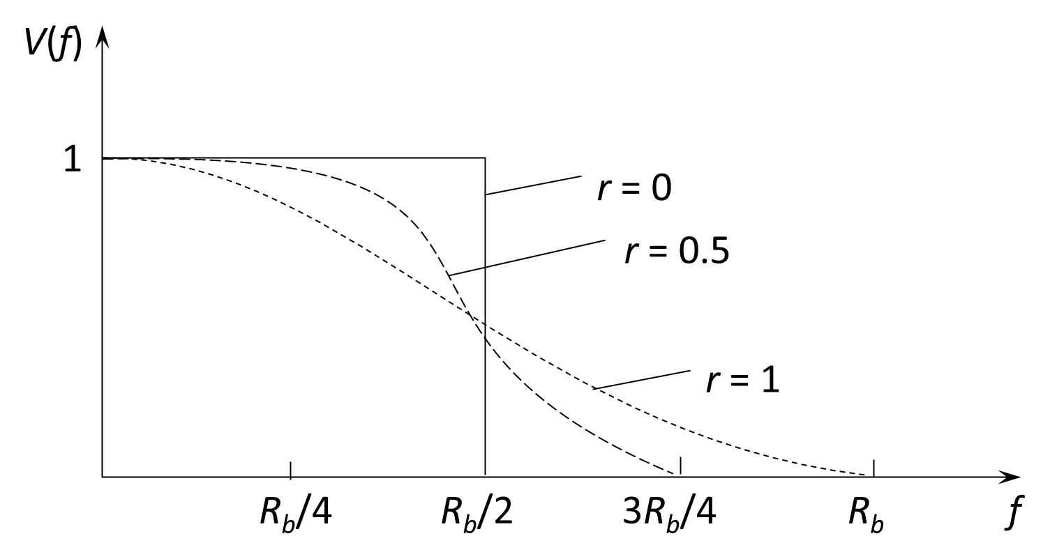
ISI can be controlled through appropriate pulse shaping. A widely used solution is the raised-cosine filter, whose impulse response is illustrated in Figure 2.29. The raised-cosine response is designed so that, at the ideal sampling instants, the contributions from all neighboring symbols are zero, thereby eliminating ISI under ideal conditions. The roll-off factor r controls the excess bandwidth beyond the minimum Nyquist bandwidth. A roll-off factor of r = 0 corresponds to an ideal brick-wall frequency response, which is unrealizable in practice; typical systems therefore use values in the range 0.2–0.5 as a compromise between bandwidth efficiency and practical implementation.
In practical digital links, the raised-cosine response is implemented by splitting the filtering equally between the transmitter and the receiver. A root-raised-cosine (RRC) filter is applied at each end so that the combined response of the link is raised-cosine. This approach minimizes ISI while producing realizable pulse shapes and efficient use of bandwidth.