
Options for BLOS communications
Radio communications techniques are normally categorized in accordance with the propagation mechanism employed for the transmission of radio-frequency energy. The following sections provide a very brief description of those mechanisms, focusing on those that are useful for RF BLOS communication. 3
Ground waves
As illustrated in Figure 1, some of the RF energy radiated by an antenna will travel directly (provided it is within line-of-sight) to the receiving antenna in what are called direct waves. A further portion of the energy will be directed towards the ground, be reflected, and then received by the antenna—these are called ground-reflected waves. The combination of the direct and the ground-reflected waves is called space waves. In addition, some of the energy is propagated by surface waves and the combination of space waves and surface waves are called ground waves.
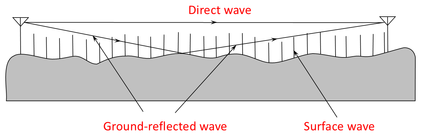
Space-wave propagation travels line-of-sight so, while there must be sufficient strength signal at the receiver for the link to work, most ground-based radio systems are terrain-limited rather than power-limited.4 That is, the curvature of the Earth constrains the extent of the line-of-sight between two low antennas regardless of how much power is used. For example, for two portable radios held waist-high (around 1 meter above ground level), the radio horizon is approximately 8 kilometers on flat terrain, even though the radios will have sufficient power to operate over tens of kilometers in free space.
If a 9-metre mast is used for the antennas for each radio, the radio horizon is extended to nearly 25 kilometers. Extended further, an aircraft at 10,000 ft would have a radio horizon of 200 kilometers to a ground terminal. Consequently, the only solutions to long-range, space-wave communication are to elevate the one or both antennas, or to place a repeater between the terminals, or both. As discussed in the following sections, the repeater is also often elevated to a convenient hill top or tower, to an airborne platform, or to a space-borne platform.
Surface waves, as the name implies, travel along the surface of the ground supported by currents flowing in the ground—the wavefront is supported between the Earth’s surface and the ionosphere. The attenuation (and therefore the range) of the wave is frequency-dependent, so that surface waves require very low frequencies which have very low bandwidths and require large antennas. Very-low frequency (VLF) surface-wave propagation can support communications around the world but such systems have very large antennas, and the small bandwidths available only allow very low data rates of a few bits per second. Low-frequency (LF) and medium-frequency (MF) broadcasting also makes use of surface waves but the ranges are small—300 kilometers for LF and 100 kilometers for MF. Given the very short ranges of HF surface-wave propagation, the mechanism is not useful for long-range communication and is not considered further here.
Sky waves
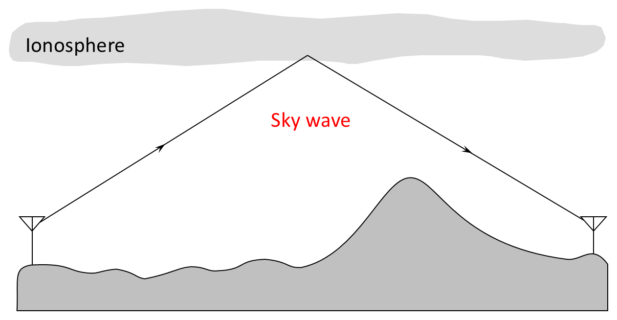
As illustrated in Figure 2, sky-wave communication utilizes the ionosphere to refract waves back to Earth, providing a mechanism for propagating over very long distances.5 The refraction mechanism is frequency dependent with the available frequencies depending on the state of the ionosphere. In general, the sky-wave window is from 2-30 MHz, with the higher frequencies only being available during periods of high solar activity. The communication range of sky waves depends on three main factors: the frequency used, the angle of transmission, and the power of the transmitter.
As illustrated in Figure 3, a higher frequency is refracted by a higher layer of the ionosphere, leading to longer ranges. Single-hop HF sky waves have ranges (skip distances) between approximately 100 kilometers (using the lower E layer of the ionosphere) and 3,500 kilometers (using the F layer). Consequently, unlike all other forms of radio communication, HF range is chosen by selecting an appropriate frequency—the higher the frequency, the higher the layer of refraction, the longer the range. At the higher extremity of the sky-wave window, the wave will no longer be totally internally refracted and will pass on out into space. It should also be noted that there is a minimum skip distance dictated by the highest angle of transmission possible from the antenna—the range is often referred to as the skip zone or the dead zone. Further, the ionosphere suffers from considerable variation in its intensity over the day, through the seasons and across years—selection and use of an appropriate frequency therefore requires considerable management.
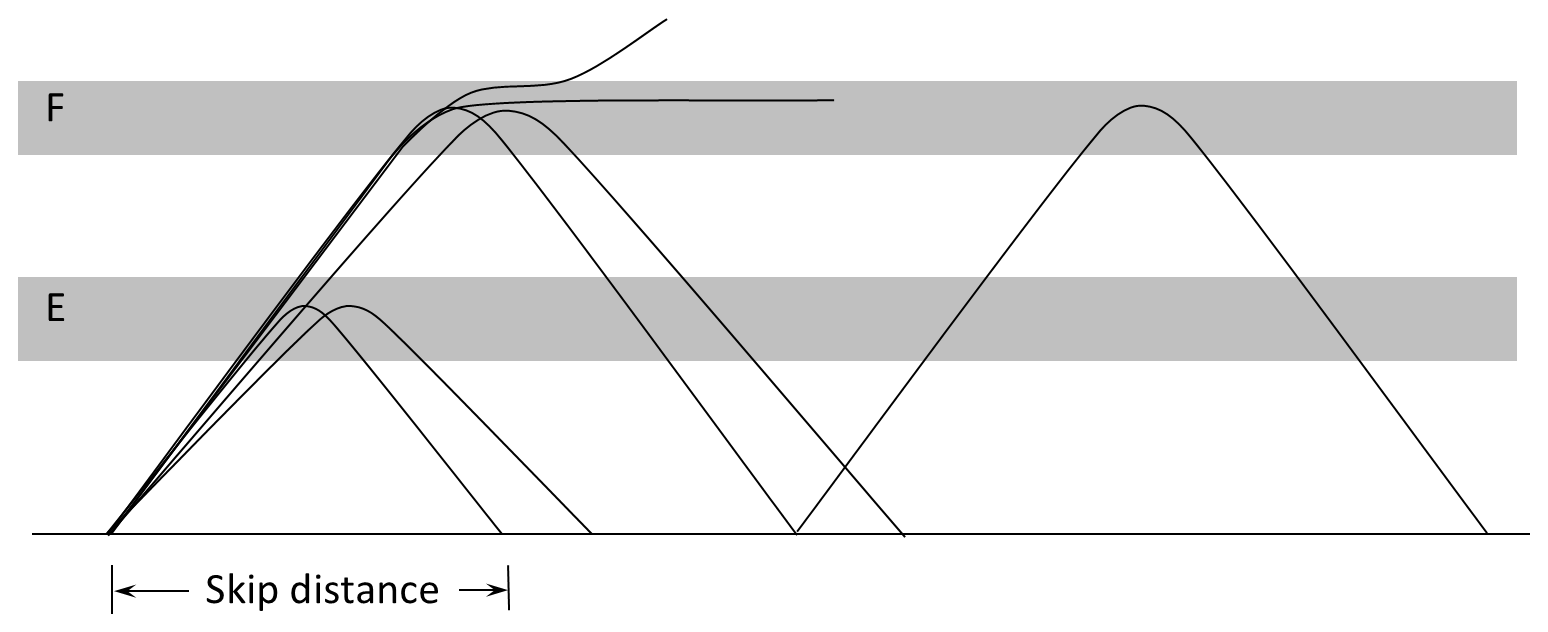
Figure 3 also illustrates that the same ionospheric layer can be used to achieve longer ranges by lowering the angle of elevation at the same frequency. Additionally, the range of the transmission can be increased with higher power, to allow multiple hops of the transmission.
Scattered waves
Scattered-wave techniques make use of turbulence in the troposphere (troposcatter)—illustrated in Figure 4—or ionosphere (ionospheric scatter), or a result of ionized meteor tails (meteor burst). Ionospheric scatter and meteor-burst techniques have very low data rates (a few tens of bits per second) and are rarely used. Troposcatter techniques are, however, used in both commercial and military networks.6
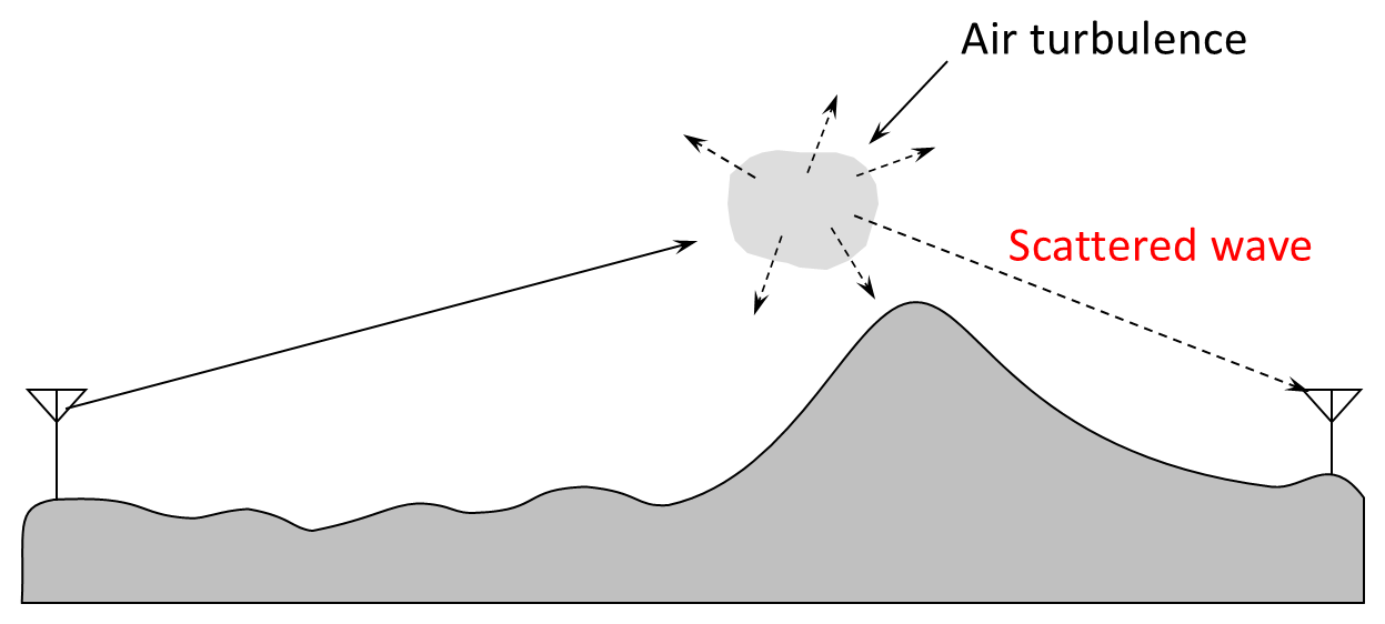
Troposcatter paths vary in length from about 100-150 kilometers to over 2000 kilometers. The maximum path attenuation including deep fades is very high, requiring the use of high-transmitted powers; low-noise sensitive receivers; and high-gain parabolic antennas. Antennas are parabolic, with diameters ranging from a few meters to tens of meters. Frequencies used are between 300 MHz and 5 GHz.
Although troposcatter communications have traditionally required large antennas and expensive receivers, they have provided very important backbones for telecommunications networks, spanning distances over which radio relay was not possible. With the advent of relatively cheaper satellite communications systems, troposcatter links have been replaced by satellite links for most BLOS applications.
However, modern technologies in the form of digital signal processing and phased-array antennas are greatly easing the previous difficulties of troposcatter, which is included in these discussions because the next decade will see a significant resurgence in the use of troposcatter systems. 7
BLOS range extension through repeaters
High-capacity communications require high-channel bandwidths, which require the employment of high frequencies. Unfortunately, frequencies above 30 MHz propagate via space wave, which is limited to line-of-sight. As mentioned earlier, the only solutions, therefore, to long-range space-wave communication are to elevate the two antennas, or to place a repeater between the terminals, or both. There are three principal repeater-based systems:
- Radio relay. In terrestrial radio-relay systems, repeaters are placed on towers on hill tops every 20–30 kilometers to overcome the limitations of line-of-sight of the microwave frequencies employed.
- Satellite. While there clearly is much more involved, a satellite communications system is basically predicated on the ability to take this range extension to the limit through the deployment of a very high radio repeater—in geostationary orbit, the repeater (called a transponder) is 36,000 kilometers above the Earth’s surface. At this greatly increased height the repeater provides much longer ranges (covering some 43 per cent of the Earth’s surface from geostationary orbit and approximately 5 per cent from low orbits).
- Airborne platforms. Sub-space (that is airborne, rather than space-borne) platforms provide similar services to satellites but do so from a repeater placed in the stratosphere rather than in space—this lower altitude provides less coverage but still can cover an area within a 500-kilometre radius (1000 kilometers between ground-based users). Airborne platforms, therefore, offer a viable alternative to satellite communications, with the potential to deliver a broader range of services more cost effectively. Further extension in coverage can be provided by cross-linking between platforms.
The range-capacity-mobility trade-off
Utilizing one of the radio-frequency propagation mechanisms, the communications systems discussed in the previous section provide ranges that vary from several hundred to thousands of kilometers, with capacities from hundreds of bits per second to hundreds of gigabits per second, and with degrees of mobility varying from small systems that are operable on-the-move to large fixed installations.
As a vehicle for considering the utility of any given system, it is useful to note that an ideal communications system has three principal attributes: long range, high capacity, and high mobility.
- High-capacity communications. High-capacity communications can be achieved by the use of a cable, optical fiber, laser through air, or by RF in the VHF and higher bands, or by scattered-wave communications. High-capacity channels are not available in the lower RF bands due to the limited bandwidth available in these bands.
- Long-range communications. Long range can be achieved by utilizing VLF/ELF surface-wave or sky-wave propagation. Further, range can be increased by using an elevated antenna or a (probably elevated) repeater with direct-wave propagation at VHF or higher frequencies. Additionally, long range can be achieved by the use of scattered-wave communications or the use of a cable or optical fiber.
- High-mobility communications. High mobility cannot be achieved using either cable or optical fiber and requires the use of RF communications employing small terminals with small antennas.
As can be seen from the preceding discussion, the simultaneous delivery of all three of these attributes is problematic, and a communications system may be able to exhibit two of them but not all three at once. It is useful, therefore, to revisit the attributes by considering them in pairs:
- High-capacity/long-range communications. High capacity and long range can be achieved by the use of cable or optical fiber, scattered-wave communications or line-of-sight RF communications with directional antennas or high-transmit powers. All these solutions limit mobility.
- High-capacity/high-mobility communications. High capacity and high mobility can be achieved by line-of-sight communications using low, omnidirectional antennas, although they are limited by the curvature of the Earth and other intervening terrain and obstacles, such as buildings and vegetation. For communications close to the Earth, range is also limited by the use of low-transmit powers due to the mobility required of the terminals, which requires small terminals with limited battery life. All these issues result in limited ranges.
- Long-range/high-mobility communications. Long range and high mobility are achieved by the use of VLF/ELF surface-wave communications, sky-wave communications from large platforms, or by the use of an elevated relay of line-of-sight communications. Although they provide long ranges, the capacity of VLF/ELF surface-wave communications is limited by the extremely small bandwidth available. Long-range, line-of-sight, radio-relay communications systems have high capacity but provide very limited mobility. Sky-wave communications systems support high mobility but with low capacities.
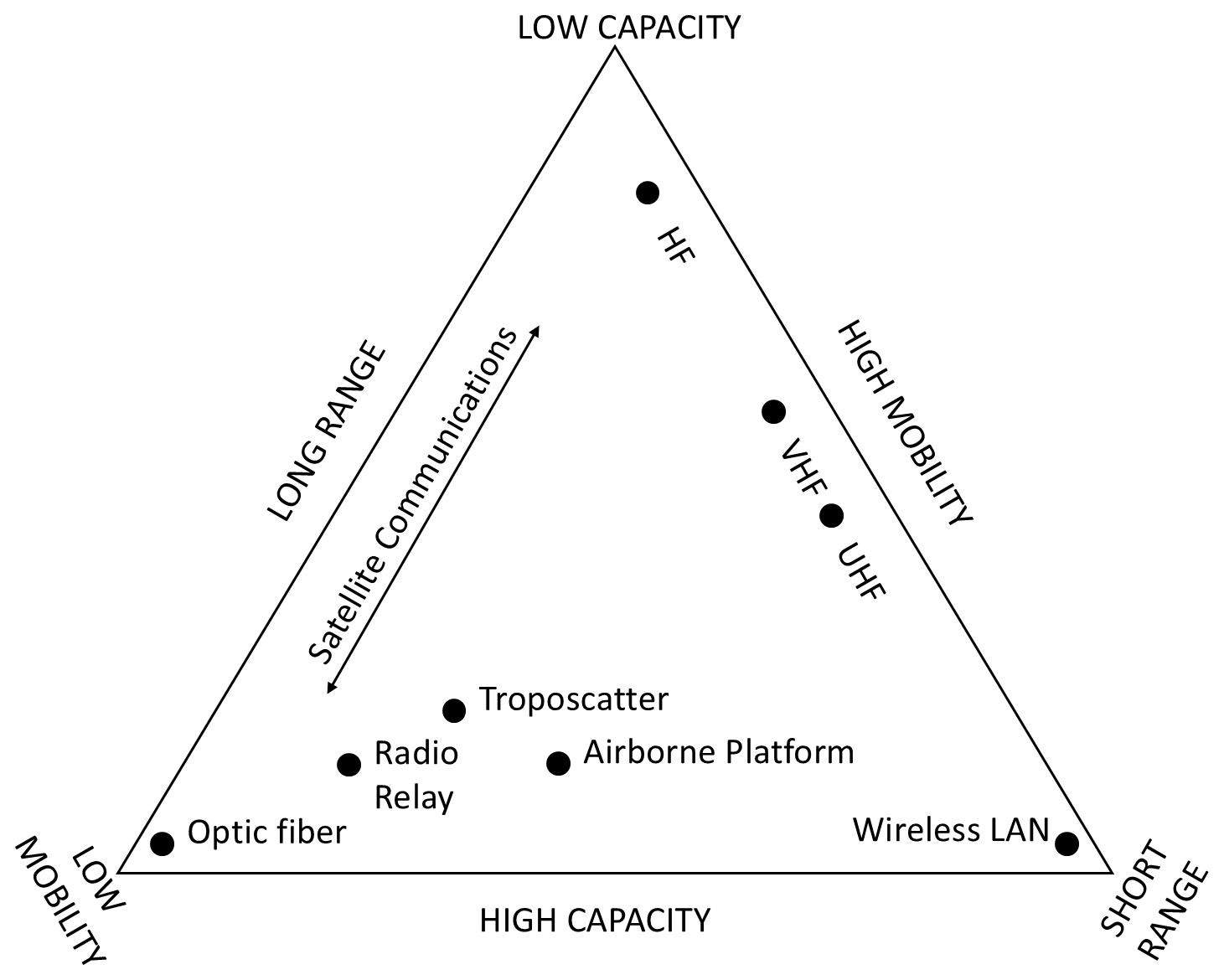
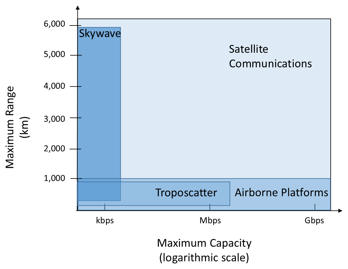
The trade-off between range, capacity and mobility is illustrated in Figure 5 for a number of communications systems. Figure 6 shows the maximum range versus the maximum capacity for the four radio-frequency systems that are useful for BLOS communications: HF sky wave, troposcatter, satellite communications, and airborne communications platforms.
The dominant utility of satellite communications is immediately obvious—capacities from low to high can be provided over ranges from short to long. None of the other systems can compete in that regard—HF communications can compete on range but has miniscule capacity by comparison; troposcatter and airborne platforms have much higher capacities than HF (with airborne platforms having much higher capacity again than troposcatter) but both are well short in range compared to satellite communication. Consequently, the ADF (and just about every other defense force and commercial organization) has embraced satellite-based systems as the principal means for long-range communication.
Endnotes
- [3] Descriptions of communications modes contained here are necessarily brief and therefore occasionally superficial. Full details of the modes are available in M. Ryan, M. Frater and M. Pickering, Fundamentals of communications and information systems, Argos Press, Canberra, 2011. back
- [4] For more detail, see T. Maclean and Z. Wu, Radiowave propagation over ground, Chapman & Hall: London, 1993; and R. Collin, Antennas and radiowave propagation, McGraw-Hill: New York, 1985. back
- [5] Further detail on sky-wave communications can be found in J. Betts, High frequency communications, The English Universities Press Ltd: London, 1967; G. Braun, Planning and engineering of shortwave links, Siemens Aktiengesellschaft (John Wiley & Sons): Berlin, 1986; J. Goodman, HF communications: science and technology, Van Nostrand Reinhold: New York, 1992; and N. Maslin, HF communications, Pitman: London, 1987. back
- [6] For more detail, see G. Roda, Tropospheric scatter radio relay links: guide to design and implementation, Applicazioni Radio Elettroniche SPA: Castallanza, 1986. back
- [7] See for example: J. Keller, “Military wants to develop RF phased array common modules for the defense industry”, Military & Aerospace Electronics, 1 May 2018. https://www.militaryaerospace.com/defense-executive/article/16707322/military-wants-to-develop-rf-phased-array-common-modules-for-the-defense-industry, accessed 8 December 2019. back
- [8] M. Ryan and M. Frater, Tactical communications for the digitized battlefield, Artech House: Boston, 2002. back