
Volume 16, Number 2, July 2013
A Tool-Agnostic Architecture Approach To Model-Based System Engineering
- 1 Jacobs Australia, Jacobs House, Canberra, Australia. An earlier version of this paper was presented in the System Engineering and Test and Evaluation Conference (SETE) 2013, Canberra, 29-31April 2013
Abstract
The Australian Department of Defence is on the cross-roads of transitioning from DoDAF Version 1.5 to AUSDAF Version 2.0, which is a variant of DoDAF Version 2.0. Whilst the philosophy between these two versions of the framework are distinctly different, the Systems Engineer (SE) often receives a mix of Defence clients adopting either one of the pseudo architecture standards for specification development. In order to accommodate this spectrum of customers’ methodology recommendations, the aim of this paper is to address the diverse range of clients. Attention is given, not only to the execution of the methodologies, but also to the approaches we take to align with the Australian Defence two pass approval process. In this paper, a tool agnostic process for architecture development is introduced to support most architecture tasks performed in Defence. Furthermore, the process incorporates association of the process artefacts with a few acquisition-based standards, which often used by most systems engineering tasks.
Introduction to defence architecture and the relationship with mbse
The intent of architecture is to provide an open, vendor-neutral model of a collection of business, systems, and services, but independent of technologies, to be considered for capability development. Despite significant work to improve engineering practices, systems engineers continue to be presented with difficulties in the design, construction, deployment and evaluation of new capabilities. Numerous past attempts to resolve this challenge have been presented, incorporated [1], or promoted as best practice [2], and in some cases even legislated by law [3]. While there is a consensus on the importance of the architectural level of systems development, there are various ways to achieve this aspiration.
Assuming that an architectural approach is adopted by the systems engineering team, one of their first questions might be: Why should I undertake architecture development using Model Based Systems Engineering (MBSE)? MBSE is an initiative promoted by The International Council on Systems Engineering (INCOSE) to support good systems engineering practice. Although it was noted by the Australian Defence Organisation (ADO), namely the Capability Development Group (CDG) and Defence Materiel Organisation (DMO), it is not formally mandated by both organisations at this stage. However, MBSE has been shown to improve design quality and to better support program management than non-MBSE based approaches [4]. The architecture models are a means of preserving the conceptual integrity of the system over time, and using a model instead of textual based documents can enable better configuration management.
The INCOSE definition does not mandate a standardised approach to accomplish the MBSE concept, but instead it recommends that the SE develop an end-to-end model to support most common systems engineering activities, such as design, analysis, and verification and validation (V&V). Whilst employing a standardised framework, such as Department of Defence Architecture Framework (DoDAF), is likely to be one the most viable strategy, other approaches do exist [4]. To name a few:
- IBM Telelogic Harmony-SE method;
- INCOSE Object Oriented Systems Engineering Method;
- IBM Rational Unified Process for Systems Engineering;
- Vitech Model Based System Engineering Methodology;
- OMG’s Model Driven Architecture;
- MITRE’s Activity Based Modelling; and
- Ad hoc methods by combining a suite of tools, such as ARENATM, MS OfficeTM, VisioTM, MatlabTM, and SQL.
The general assumption is that, one does not need to employ an architectural framework to satisfy the MBSE concept. As an example, an engineer could model a capability by employing Microsoft ExcelTM, AccessTM and VisioTM, without satisfying any of the DoDAF guidance, but yet could still label this methodology as MBSE. This rationale is justified, because the SE could employ the suite of combined ExcelTM/AccessTM/VisioTM output to support most common system engineering activities. If additional works are invested, the design data stored in these tool can be made interdependent, however, the designs are not expressed in a standardised way. Admittedly, it is not the most elegant solution, it does work for most simple projects.
Assuming the defence architecture approach is adopted, we can argue that MBSE is almost being executed by default, leveraging either the Vitech Model Based System Engineering Methodology, or the OMG’s Model Driven Architecture (MDA) concept, or MITRE’s Activity Based Modelling (ABM). This rationale is justified, because all of these methods require some sort of computerised tool to capture, process, and store the system engineering design data in a structured model. These approaches not only eliminate the need to put all design data in a paper format, but also allow the SE to generate a suite of ‘fit-for-purpose’ outputs to support their design, analysis, and V&V activities from a single data model source.
Applying MBSE on an architecture framework is a significant paradigm shift in systems engineering that uses models to separate logical model from the underlying platform technology. Admittedly, this concept is not exactly novel, when it is compared with the Australian Government two-pass process [5]. The two-pass process is essentially a mirrored image of the MBSE concept, but Defence practitioners are free to roam with any methodology to satisfy this process. MBSE, however, has the advantage of significantly improving the return-on-investment, through increased reuse, and configuration management is improved using models instead of documents. The approach of using architecture models is likely one of the most logical means to preserve the conceptual integrity of the system over time. In the following section, this paper discusses a range of tool agnostic methods that cover most Defence systems engineering tasks. Following that, we introduce the tool-agnostic methodology consideration. Finally, a cross correlation matrix between DoDAF viewpoints, MIL-STD-498 [6] and DMO-CDRL-DID [7] is introduced to reinforce the advantage of data reuse for the architecture information.
Defence architecture development process and methodology
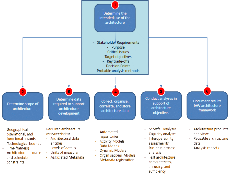
Both DoDAF 2.0 and DoDAF 1.5 recommend a six-step Architecture Process illustrated in Figure 1. For most architecture development, the six-step process is applicable when sufficient supporting materials are available. However, the suggested process does not replace the architecture development methodology, because the process does not address the “how”, which comprise the sequence, relationship, data storage, and technical representation method required to assemble an end-to-end architecture. The six-step architecture development process, often implemented with minor tailoring, is outlined in Figure 1.
Several methodologies exist for Defence architecture development. While this paper does not promote a specific approach, the selection of such methodology is often determined by the tool employed—which can be outside the scope of the SE decision. Based on our past experiences, the most common approaches suitable for Defence clients are Vitech based MBSE methodology, Activity Based Modelling (ABM) methodology, Unified Profile of MoDAF and DoDAF (UPDM) architecture and Data Centric Architecture Development methodology. In the following sections, we shall address the way each methodology could support the Defence two-pass capability development/acquisition process. In order to avoid the duplication of design work, the emphasis will be on re-using architecture data to satisfy the open standards such as MIL-STD-498, or DMO CDRL Data Item Descriptions (DIDs) requirements.
Activity based modelling methodology
ABM was developed to establish a common means to express integrated architecture information consistent with the intent of DoDAF 1.0, and the legacy Common Architecture Data Model (CADM). While it was developed as a ‘tool-independent’ approach, the methodology was fully incorporated in the IBM System ArchitectTM tool set. ABM uses data centric approach for architecture element, and product rendering instead of a product centric approach. The approach taken by ABM based on a core set of architecture building block elements, which enable several architecture objects to be automatically generated, and several architecture viewpoints to be automatically rendered. The ABM was designed to capture ‘static’ activity/information flow architectures models to transition them to ‘dynamic’ executable process models for analysis. When the ABM approach is adopted, SE usually follows a four-step process to execute the methodology.
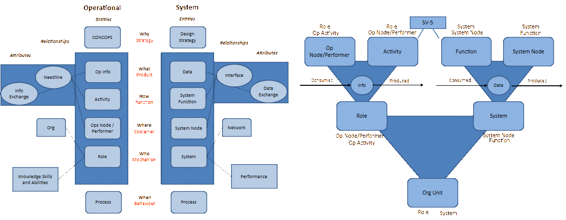
Step 1—Align Operational and System Architecture objects, and divide all the object classes into: entities, relationship and attributes. The alignment can be summarised in Figure 2. Step 2—Mapping the four operational (Op Info, Activity, Op Node/Performer) and four system architecture entities (Data, System Function, System Node, System) to provide the foundational building blocks of an integrated architecture. The core entities relationship is summarised in Figure 2, where the mapping is conducted in a way, such that Operational Activity (System Function) that produces and consumes information (Data) is performed at an Operational (System) Node by a Role (System). Step 3—When the ABM approach is taken, we should employ a tool to enter manually all the available information. Given the meta model resides in the tool, it is already organised as discussed in Step 2, most of these mappings are already taken care by the tool in the background. Step 4—Several DoDAF relationships and attribute architecture object classes (such as Information Exchange in OV-3) can be generated automatically from the tool.
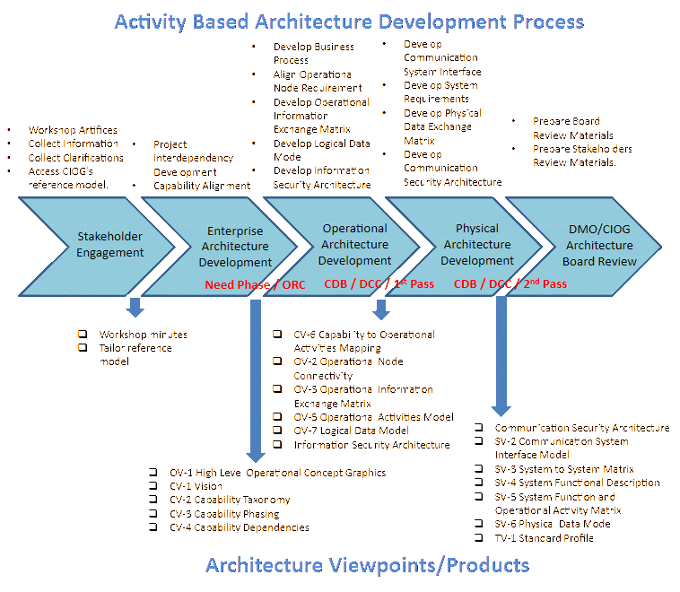
The ABM approach provides the SE with a set of integrated architecture products, which can tailor the DoDAF’s viewpoint artefacts to support the Defence two-pass acquisition framework. Details of the task, and the product development process is depicted in Figure 3 where the proposed tasks and deliverables are outlined in the diagram.
Vitech’s model based system engineering (mbse) methodology for defence architecture development
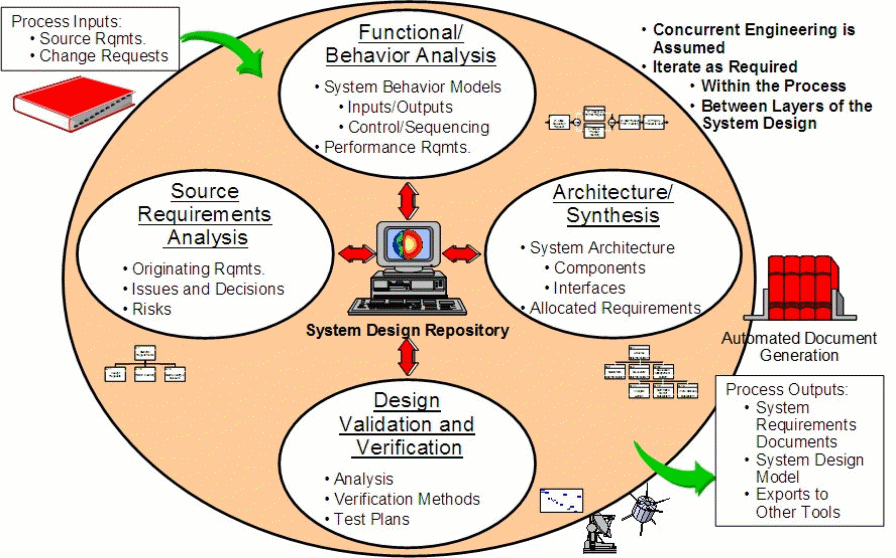
Vitech offer a MBSE methodology via the company tutorial and publications [8]. The methodology illustrated in Figure 4 is based on four primary concurrent systems engineering activities through the System Design Repository (SDR) inside the tool. Each of the systems engineering activities, namely the Functional / Behaviour Analysis, Architecture / Synthesis, Design Validation and Verification, and Source Requirement Analysis, are linked within the context of associated ‘domains’.
When the Vitech MBSE methodology is adopted for architecture development, it is critical to explain to the stakeholders how the Vitech’s MBSE System Definition Language (SDL) is employed to manage model artefacts. This means the SE team should treat the consultation process as the first priority to ensure all stakeholders reach an agreement upon information model (Meta Model) in the form of a schema prior to project commencement. Such a schema has a number of uses, such as providing a structured, common, explicit, context-free language for technical communication. Based on the agreed schema, the SE team could employ the Vitech tool (CORETM) to execute a four-step approach for the architecture development.
Step 1: Build a model to describe the problem and the solution space by employing Vitech’s SDL. This step includes the development of a set of explicit and consistent semantically-meaningful graphics, which could help the development team facilitate model traceability, consistent graphics, automatic documentation and artefacts, dynamic validation and simulation, and promotes more precise communication. Step 2: Utilise Vitech’s MBSE system design repository. Step 3: Engineering the system horizontally before vertically. Step 4: Employ the tool—CORETM, to collate the design data, and conduct the design based on the model.
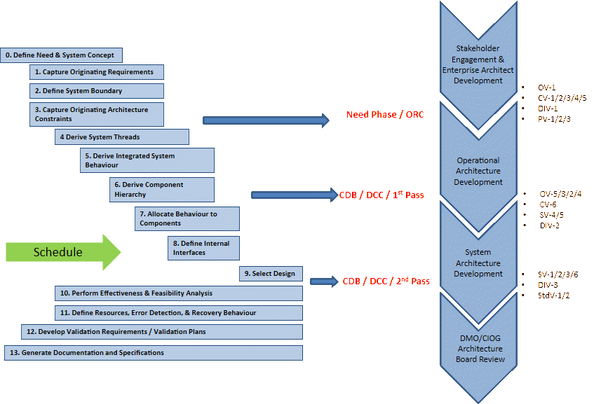
To employ the Vitech’s MBSE approach, the SE could adopt an incremental development technique known as the “Onion Model” proposed by Vitech [9]. This methodology allows the systems engineer to complete the interim solution at increasing levels of detail during the system specification process. The Onion Model iterates system engineering activities at each layer. Once one layer of system design is completed, the design team can start exploring the next layer. When an agreement is reached with the stakeholder with sufficient layers of detail, the design is completed. The Onion Model can be viewed as a set of system engineering activities conducted in parallel with the Defence two-pass approval timeline. While the schedule can be read as increasing in time from left to right in these SE activities, their design artefacts can be adopted to support the two-pass requirements as proposed in Figure 5.
Defence architecture development methodology using updm-based mbse
The Unified Profile for DoDAF and MODAF (UPDM) [10] [11] initiative was started by the members of INCOSE and OMG. UPDM provides a consistent, standardised means to describe DoDAF 2.0 and MODAF 1.2 architectures in SysML/UML-based tools, as well as a standard for interchange. The concept employed by SysML such as, parametrics, blocks, complex-ports, enhanced activity modelling, and cross cutting constructs, are incorporated within the profile to improve the system-to-system design expression. One important aspect of UPDM is the Domain Meta Model (DMM), which is compatible to the DODAF 2.0 Meta Model (DM2). The UPDM group created the DMM, which is based on UML Class model, to represent the concepts in DoDAF and MODAF. The traceability between the DMM and the UPDM profile model were also addressed in the UPDM Version 2.0. The concepts common to both DoDAF and MODAF were captured in a core package, with DoDAF and MODAF packages also being created for their specific elements. The DMM concepts were then mapped to corresponding stereotypes in the UPDM profile, which was analysed and re-factored to reflect language architecture, tool implementation, and library reuse considerations [12].
Since the employment of UPDM is driven by the need of UML/SysML standardised structure-representation, the SE team often invests extra effort to define architecture data requirements up-front, when UPDM is adopted for the development. For Example meta-data type such as, TypicalOperationalActivities and OperationalActivities, means two very different types of data in UPDM/DoDAF 2.0. Attention is given by the SE team to ensure an accurate data set is collected from the stakeholders in the appropriate setting. The proposed UPDM-based architecture development methodology is depicted in Figure 6.
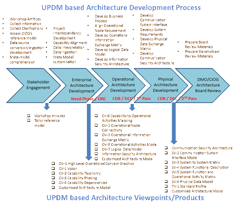
The methodology is similar to ABM, but the emphasis is placed on the configuration control, development, and the extension of UPDM’s meta-model. Our experience suggests that meta-model tailoring is almost an unavoidable step, if UPDM is adopted, because most non-technical stakeholders are unlikely to comprehend the architecture model in the SysML/UML ‘wiring diagram’. It is almost certain that, some kind of customised data-visualisation will be required to accompany with the UPDM approach. Request of incorporating wider range of data, which is outside the scope of DM2/DMM, will certainly occur between these events.
Methodology selection
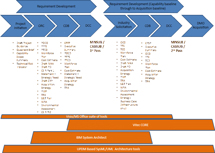
When architecting a capability, the SE should not be biased to any specific MBSE methodology that is employed. However, as a general observation, we have seen the strength of each methodology in the past, during various stages of the acquisition activity as depicted in Figure 7. For example, Vitech’s CORETM-based MBSE is good for functional analysis, and it has distinct advantages when the model is being employed to manage the actual acquisition activities. ABM based approach is good at quickly capturing the logical/physical relationship during the pre-first pass based activities, and a tool like IBM SA is easy to manipulate when the model needs to be completed in a tight time frame. Due to its UML/SysML backbone, UPDM based approach certainly gives the system engineering team the widest pool of talents available for selection. UPDM is an industry-standard based concept, which means the cost of long-term ownership to the model is relatively low, when compared with other methods. The functionality of each of the packages overlap with the others, which suggests that no single package is ideal for the full capability development and acquisition life cycle. In the view of the author opinion, choosing a single package is often not an optimal approach. A single package may be ideal for a particular phase of the project, and used throughout the whole project even though it is not ideal at every stage.
While static model development is an important step, dynamic simulation is just as critical to support the MBSE concept. All three methodologies discussed have a host of simulation engines to assist model refinement, however, one has to understand the purpose of the simulation, prior to commit to in a particular simulation tool. This paper proposes to employ the most appropriate simulation tools to refine the model development at different stages of the design process. Figure 8 summarises the collective experiences gained from various past Jacobs Australia projects.
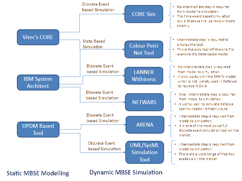
Some tools are designed to simulate complex system, whereas the others are less computational intensive, but have the advantage of visual appeal. Alternatively, some tools are relatively easy to use, but often limited by the interoperability with a wide range of commercial-off-the-shelf (COTS) architecture tools. The SE team should work with the stakeholders to ensure the following points are satisfactorily addressed.
- Is the simulation tool essential to support the static model development?
- What is the cost-of-ownership of the simulation model for the short/long term?
- Would the quality of the static model be degraded if the simulation tool is not employed?
- Would the decision-makers need sensitivity analysis to support their decision?
- Do we need intermediate step(s) to transform the static model for dynamic simulation?
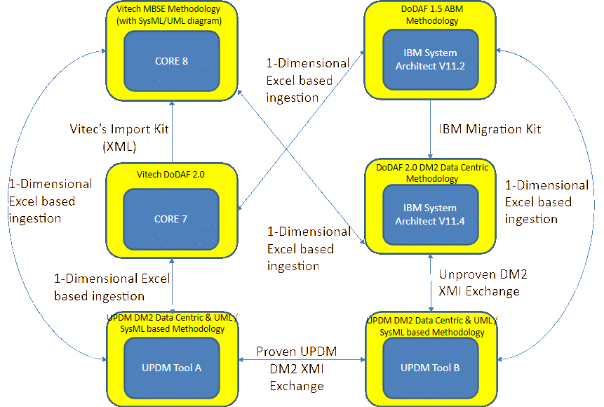
Although a specific methodology may have been selected at the start, the SE may need to switch from one methodology to another in the middle of the development activities. Should this event occur, it is critical to understand the schema/meta-model behind each of the tools to support the methodology discussed. DoDAF 2.0 promotes the concept of DoDAF Meta Model (DM2), where the tools are designed to interchange their background data without distorting the front-end representations. At the time of preparing this paper, UPDM Version 2 and IBM SA Version 11.4 complied with the DM2 standard. Vitech’s CORETM complied with the DoDAF 2.0 Viewpoint recommendations, but is yet to comply with the DM2 guidance. Figure 9 summarises the complexity of the interchange descriptions, which highlights the interoperability requirement between tools and methodologies. DM2 compliance is a good start for a tool-agonistic approach, but our experience suggests the attributes associated with the architecture data can vary between tools. Should there be requirement for data interchange, then the SE team would assign a system engineer dedicated to manage this non-trivial ‘data-ingestion’ task.
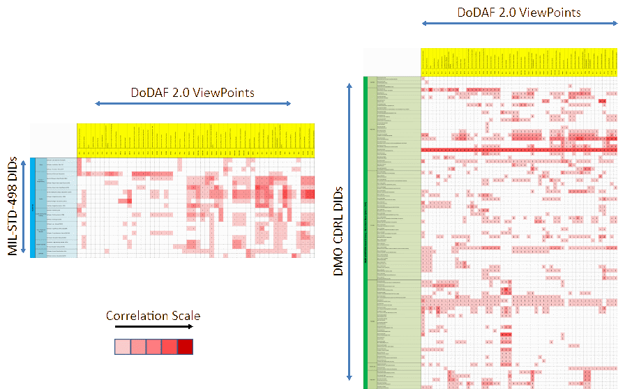
Dodaf v2.0 viewpoint, mil-std-498, and dmo-cdrl-did mapping
The concepts presented in DoDAF V2.0 are data-centric in nature, rather than product-centric as in previous versions of the DoDAF. This means the sharing of architecture data is through the use of common data that conform to the DoDAF Meta-model (DM2). Methods of collecting data, use, and presentation in the standard, such as OV-1, SV-1, SV-2, and DIV-1., are not mandated. This data-centric concept aligns with the MBSE movement, however, it is always a challenge to meet the contractual requirement, when the only deliverable is a static electronic file. This paper envisages that a hardcopy-Viewpoint deliverable will always be required as part of the Contractual Deliverable Requirement List (CDRL) to comply with the contractual obligation.
Under the new DoDAF V2.0 concept, organisations are free to tailor their presentations to suit their own needs. This means in addition to the standardised viewpoints of DoDAF V2.0, architecture developers are free to develop their own visualisations to meet the ‘fit-for-purpose’ aspiration. Some customised viewpoints, could be in the form of collated document in a standardised document template such as the Capability Development Document (CDD) suite [2], or in the form of multi-dimensional visualisation tool, such as the Defence Science Technology and Organisation (DSTO) developed Program Viewer [12]. These viewpoints are the major categories of data, arranged into useful grouping to facilitate their use. The acquisition agency has the potential to achieve a significant cost-saving by reusing the architecture data to assist the capability acquisition activities. In this way, the traceability between Needs-Requirements-Acquisition-Sustainment phases is being properly maintained by all organisations.
Amongst most engineering standards, the MIL-STD-498-DID and DMO-CDRL-DID are probably the most widely employed method to standardise engineering deliverables in DMO. Both MIL-STD-498 and DMO-DID were developed with the purpose to establish uniform requirements for system development and documentation. MIL-STD-498, however, has a software focus and details of the sustainment requirement such as logistics and project management’s requirements are not incorporated. The DMO DID is a generic approach that could support most acquisition activities in Defence. It comprises of six set of DIDs, including configuration management (CM), engineering, integrated logistics support (ILS), project management (PM), tendering, and V&V.
While MIL-STD-498-DID supports computer software engineering, the DMO-CDRL-DIDs are for more general-purpose engineering including computer hardware and software, as well as non-computer engineering products to support DMO acquisition activities. Through the identification of correlation relationships between architecture, engineering, project management and logistics artefacts, the SE team has the potential to minimise duplication, and hence reduce total acquisition cost. This approach has a number of advantages which include;
- Promote data reuse to achieve a cost-effectiveness outcome.
- Encourage synergy of acquisition tasks
- Acquisition data are stored in one single source to improve configuration control
A sample of the recommended mapping between DoDAF V2.0—MIL-STD-498 and DODAF V2.0—DMO DID are depicted in Figure 9. The mapping was constructed based on the survey of a group Subject Matter Experts (SME) in Jacobs with both architecture and systems engineering experience. The suggested mapping provides guidance on how data can be reused, or leveraged from the DoDAF V2.0 viewpoints, to reduce the cost of overall development. In some instances, data can be a direct ‘cut and paste’ to the DID’s artefacts, or in other cases, information capture in the viewpoints can be used as the basis of the CDRL development.
Conclusion
This paper has covered several tailored approaches that systems engineering can offer Defence capability development project when architecture framework is employed. While they are often seen as tool-independent strategies, in reality, most of them are customised to a specific class of tool set. In this paper, we have described an approach to the DoDAF recommended process, and three tool-agonistic architecture development methodologies. We have listed the steps in each of the methodologies, and mapped them with the Defence’s two-pass approval process. However, after following all the rules and suggestions, one of the most important things to remember is that there is no single architecture development methodology to fit all tasks. This is where the systems engineering experience comes in, to tailor the methodology together with customer to optimally fit with the original intent. The tools nominated for the architecture development will undoubtedly affect the methodology choices. However, we can only exploit the quality of our architecture by using the architecture model in applications for which it was designed.
References
[1] T. Wheeler, and M. Brooks, “Experiences in Applying Architecture-Centric Model Based System Engineering to Large-Scale, Distributed, Real-Time Systems”, MITRE Journal, 2007.
[2] DoDAU, Defence Capability Definition Documents Guide, Director General Standardisation, 2007.
[3] US Federal Law, Clinger-Coher Act, United States of America, 1996.
[4] J. Estefan, Survey of Model-Based Systems Engineering (MBSE) Methodologies, INCOSE, 2008.
[5] DoDAU, The Defence Capability Development Handbook, Department of Defence, 2011.
[6] USDoD, MIL-STD-498 Military Standard—Software Development and Documentation, USDoD, 1994.
[7] Defence. Contracting—ASDEFCON Asset Library, [Online] Available at: http://www.defence.gov.au/dmo/gc/asdefcon/ asset_lib.cfm, 2013.
[8] D. Long and Z. Scott, A Primer For Model-Based Systems Engineering, Vitech Corporation, 2011.
[9] Vitech, Model-Based System Engineering using CORE Course Notes, Vitech, 2010.
[10] M. Hause, Model-Based System of System Engineering with UPDM, Atego, 2010.
[11] OMG, Unified Modeling Language: Superstructure, Object Management Group, 2004.
[12] P. Pong, K. OShea, and G. Bulluss, Fit-for-Purpose Visualisation of Architecture to Support Defence Capability Decision-Making, DSTO, 2012.