
Volume 16, Number 2, July 2013
Effect Of Terrain Bounce Jamming On Missile Guidance In A Sea Environment
- 1 Institute for System Studies and Analysis, Defence Research and Development Organisation, Metcalfe House Complex, Delhi-110054.
Abstract
The signal received by the missile seeker is processed in the monopulse receiver to determine the direction (bearing and elevation) of the target. The sum and difference voltages generated by the signal are electronically manipulated to obtain the boresight error (angle) to the missile seeker. This angle is processed to provide appropriate guidance to the missile. In the presence of multipath in sea environment, this signal is a combination of the direct target return and a return seemingly emanating from the target image beneath the sea surface. This concept of multipath is utilized in terrain bounce jamming to jam the missile seeker. This paper focuses on the study of the effect of terrain bounce jamming on missile guidance based on analysing the boresight error to the missile seeker.
Introduction
Two types of jamming techniques are used today, direct signal jamming (DSJ), in which an electromagnetic beam of higher amplitude than the jammed signal is transmitted toward the victim radar in the same frequency band; and terrain bounce jamming (TBJ), in which the jamming signal arrives at a different angle to that of the true jammer angle. In a sea environment, TBJ presents a false target angle to the seeker, and directs the missile away from the true target.
Earlier works in terrain bounce (TB) are more focussed TB scattering and clutter reduction. These include study of the problem of adaptively cancelling both conventional clutter and terrain scattered jamming (TSJ) in airborne radar systems [1]. A new method for the suppression of terrain scattered clutter due to jamming of the radar footprint has been proposed in [2]. A method of factored processing consisting of terrain scattered interference (TSI) cancellation followed by mono-static clutter removal has been proposed in [3]. A technique for the mitigation of main-beam jammers that are spatially co-located with targets of interest has been proposed in [4]. Issues concerning TSI or hot clutter have been studied in [5]. A method for radar air-to-surface target identification in heavy precipitation has been proposed in [6]. Theoretical analysis of a hot clutter (TSI), TSJ or jammer multipath suppression method is reported in [7]. Furthermore, analysis of the TSI mitigation performance for different conditions and limitations is described in [8].
Most missile seekers use monopulse or pseudo-monopulse reception techniques for obtaining information regarding the direction of the target. In a monopulse receiver, the sum and difference voltages generated by the signal are electronically manipulated to obtain the boresight error (angle) to the seeker. This angle is processed to provide appropriate guidance for the missile. Based on the guidance, the missile changes its orientation to null the error. This paper studies the effect of TBJ on missile guidance by analysing the boresight error to the missile seeker. For this, a missile tracking a target with onboard jammers in sea environment has been simulated in MATLAB.
The rest of the paper is organized as follows: the fundamentals of TBJ are explained in section II. Assumptions have been explained in section III. Modelling of boresight error is explained in Section IV. Simulation of the engagement scenario and observations is presented in Section V. The paper is concluded in Section VI.
Fundamentals of terrain bounce jamming
The jammer should have the following properties to employ TBJ:
- A narrow elevation plane beam-width.
- A broad azimuth beam-width to extend the jamming coverage sector.
- High RF transmit power to overcome the losses associated with the terrain propagation path.
- Very low side-lobes at the horizon and above to prevent the missile from beaconing on the jammer.
- Positioned at a low altitude and transmit a noise-like continuous waveform towards the ground.
The target-missile engagement is illustrated in Figure 1. The scenario consists of a target and a missile with home-on-jam (HOJ) capability. The target has onboard ESM and a high-power non-coherent jammer. When the missile switches to search mode, its seeker transmission is detected by the onboard ESM receivers of the target and the jammer is switched on. The signal received by the missile seeker is processed to determine the direction of the target. In the presence of multipath in sea environment, this signal is a combination of the direct target return and a return seemingly emanating from the target image beneath the sea surface.
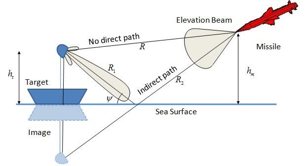
This concept of multipath is utilized to jam the missile seeker. The aim of the TBJ technique is to saturate the missile seeker by pumping power to its antenna through a reflected ray. If the missile has an HOJ capability at receiver saturation, the missile switches on automatically and will be pulled onto the image of the jammer.
In Figure 1 hm is height of missile, ht is height of target, R is the direct path between the target and the missile, ψ is grazing angle and R1 + R2 is the total indirect path from the target to the missile.
Assumptions
Assumptions used in the simulation are listed below:
- The effect of specular reflection is considered but same effect can be shown for diffuse reflection or combination of both.
- The effect of vertical polarisation signal is considered but same effect can also be shown for other polarisation signal.
- The wave height follows Gaussian distribution as it does not include any discontinuities and meets the actual or experimental data.
- The missile has HOJ capability.
- The analysis of effect of TBJ on missile guidance has been undertaken for an open-loop response. In the closed-loop case, the missile seeker attempts to null the angle error. The open loop response approach enables study of qualitative factors that affect the performance of missile guidance in the presence of TBJ.
Boresight error
The boresight error to the seeker is the angular deviation of the optical axis from a specified reference. For the computation of boresight error in the missile seeker, the following coefficients are used.
Iv.1 terrain reflection coefficient (ρt)
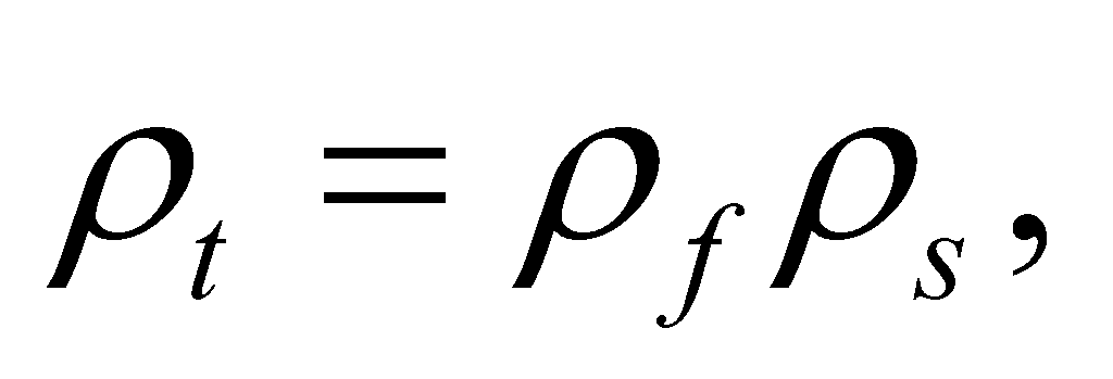
When a wave reflects from the sea surface, it suffers a change in both attenuation and phase, this change is described by Terrain Reflection Coefficient (ρt) [9]:
where, ρf is the Fresnel Reflection Coefficient and ρs is the Specular Reflection Coefficient.
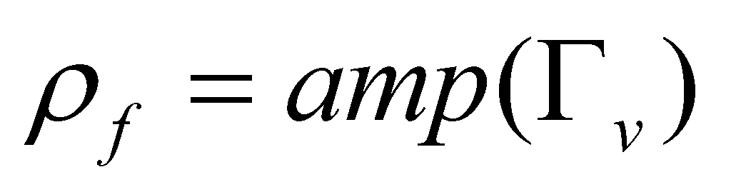
Iv.2 fresnel reflection coefficient (ρf)
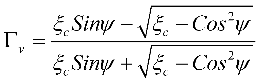
For vertical polarization wave, Fresnel Reflection Coefficient (ρf) is given as [10]:
where:
where, ξc is complex dielectric constant of seawater given by:
where, ξr is the dielectric constant of seawater, λ is the operating wavelength in metres and σ is the conductivity of seawater in mhos/m.
Iv.3 specular reflection coefficient (ρs)
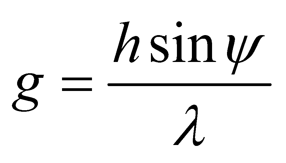
For irregular terrain, the sea surface motion can be adequately characterized by a simple representation of the wave height spectrum h and a surface roughness parameter g. These two observables are the most fundamental parameters of the model. The surface roughness parameter g is defined as [11]:
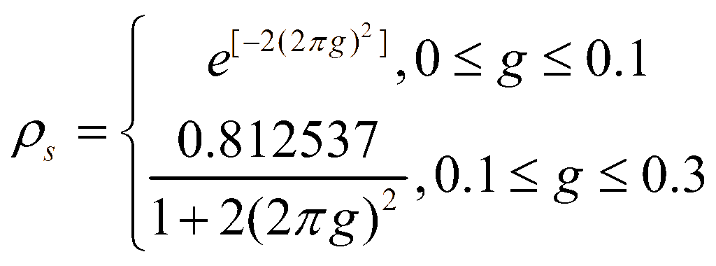
where, h is the RMS wave height and 0≤ g ≤ 0.3 for different sea states. Specular Reflection Coefficient (ρs) is computed as:
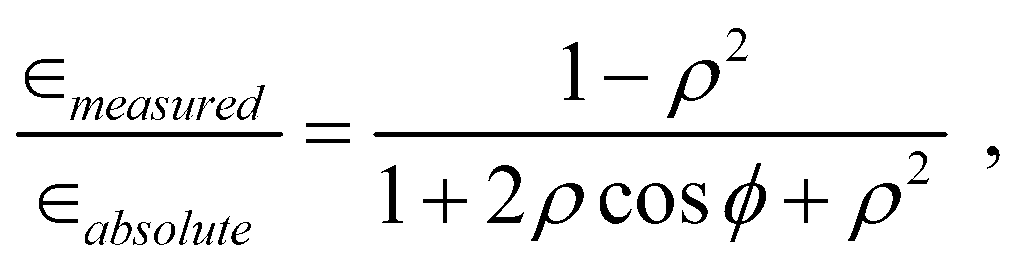
Using these coefficients, the ratio of boresight error in the presence/absence of TBJ (ϵmeasured) to the boresight error in the absence of multipath (ϵabsolute) for different sea states is computed as [12]:
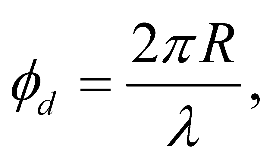
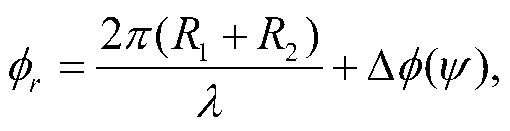
where, ϕ is sum of phase angles of the direct signal (ϕd) and reflected signal (ϕr),
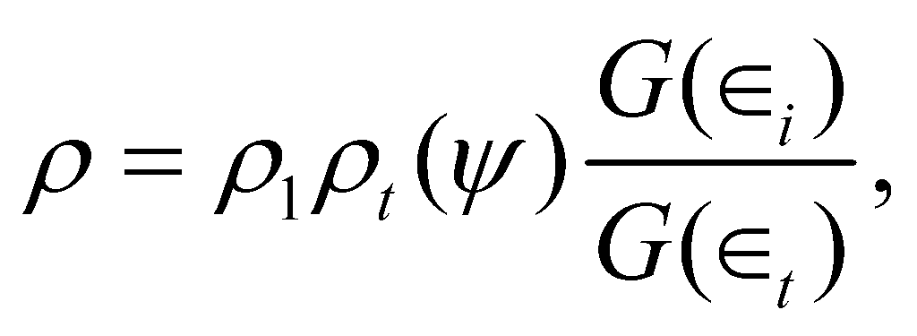
Δϕ(ψ) is phase change due to reflection from the terrain for grazing angle ψ, ρ is ratio of the amplitude of the image signal to the target signal:
where, ρ1 is ratio of radar cross sections of the image and target reflecting surfaces as viewed by the missile receiver, ρt(ψ) is magnitude of the terrain reflection coefficient with grazing angle ψ, G(ϵi) is the antenna gain in the direction of the image and G(ϵt) is the antenna gain in the direction of the target.
Power is generated to the missile seeker through the reflected ray from the sea to employ TBJ. So, the antenna gain in the direction of the image will be high in comparison to the antenna gain in the direction of the target. To study the difference in power received in the missile seeker in presence and absence of TBJ, the relative power of the return signal is computed as follows [12].
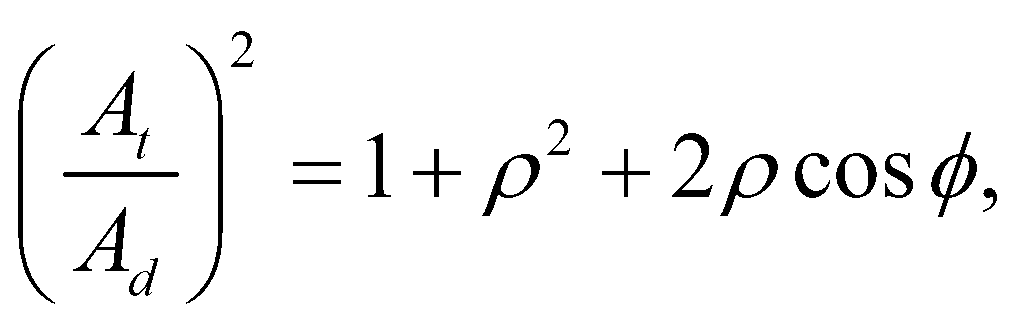
The ratio of the amplitude of total received signal to the amplitude of direct signal is given by:
where, Ad is the amplitude of direct signal and At is the total received signal in the presence of TBJ / multipath. Assuming phase of direct signal is equal to zero—that is, ϕd = 0 as reference phase.
Simulation and observation
A point mass model of a missile tracking a target has been simulated in MATLAB. Simulation starts at time t = 0 s and ends at missile’s closest point of approach to the target. The input parameters used in the simulation are shown in Table 1.
For analysis of the effect of TBJ, two cases are considered: Case 1—presence of multipath without TBJ engaged; and Case 2—presence of multipath with TBJ engaged. Additional input parameters (shown in Table 2) are used in Case 2.
| Parameter | Value |
|---|---|
| Target height | 20 m |
| Missile height | 1 000 m |
| Missile to target range | 25 000 m |
| Missile velocity | 250 m/s |
| Target velocity | 10 m/s |
| Operating frequency | 10 GHz |
| Polarisation of signal | Vertical |
| Dielectric constant of seawater | 80 |
| Conductivity of seawater | 4.3 mhos/m |
| Parameter | Value |
|---|---|
| Ratio of radar cross sections of the image to the target reflecting surfaces as viewed by the missile receiver. | 0 dB |
| Ratio of antenna gain in the direction of the image to antenna gain in the direction of the target. | 20 dB |
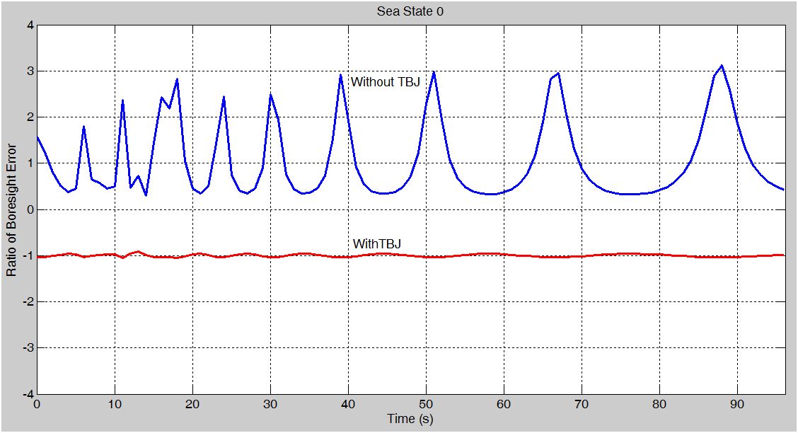
The ratio of boresight error in each simulation time for both the cases has been observed at different sea states (0 to 5). The observed boresight errors have been shown in Table 3. Simulation time versus the ratio of boresight error in absence and presence of TBJ has been plotted in Figures 2 to 7 for each sea state respectively.
| Time | Ratio of boresight error | |||||||||||
|---|---|---|---|---|---|---|---|---|---|---|---|---|
| Sea state 0 | Sea state 1 | Sea state 2 | Sea state 3 | Sea state 4 | Sea state 5 | |||||||
| T | WT | T | WT | T | WT | T | WT | T | WT | T | WT | |
| 0 | -1.0335 | 1.5667 | -1.0408 | 1.5296 | -1.0740 | 1.3263 | -1.1153 | 1.2121 | -1.1733 | 1.1413 | -1.2472 | 1.0987 |
| 10 | -0.9584 | 0.3751 | -0.9496 | 0.4575 | -0.9106 | 0.6601 | -0.8644 | 0.7675 | -0.8033 | 0.8388 | -0.7301 | 0.8844 |
| 20 | -0.9614 | 0.4003 | -0.9531 | 0.4838 | -0.9164 | 0.6841 | -0.8725 | 0.7869 | -0.8136 | 0.8537 | -0.7420 | 0.8958 |
| 30 | -0.9693 | 0.4801 | -0.9625 | 0.5643 | -0.9319 | 0.7522 | -0.8941 | 0.8397 | -0.8411 | 0.8932 | -0.7736 | 0.9253 |
| 40 | -0.9816 | 0.1620 | -0.9776 | 0.2721 | -0.9595 | 0.5518 | -0.9371 | 0.7001 | -0.9060 | 0.7963 | -0.8662 | 0.8562 |
| 50 | -1.0057 | 0.4516 | -1.0068 | 0.6345 | -1.0115 | 0.9346 | -1.0161 | 1.0034 | -1.0205 | 1.0207 | -1.0223 | 1.0221 |
| 60 | -1.0197 | 0.9827 | -1.0240 | 1.2161 | -1.0432 | 1.3162 | -1.0667 | 1.2349 | -1.0990 | 1.1649 | -1.1392 | 1.1180 |
| 70 | -1.0301 | 4.5408 | -1.0368 | 3.2726 | -1.0676 | 1.8499 | -1.1068 | 1.4779 | -1.1642 | 1.2962 | -1.2427 | 1.1989 |
| 80 | -1.0147 | 0.7105 | -1.0178 | 0.9281 | -1.0317 | 1.1502 | -1.0481 | 1.1406 | -1.0696 | 1.1084 | -1.0943 | 1.0812 |
| 90 | -0.9804 | 0.2381 | -0.9761 | 0.3460 | -0.9567 | 0.6095 | -0.9326 | 0.7430 | -0.8989 | 0.8274 | -0.8556 | 0.8790 |
| Sl No. | Case 1 | Case 2 |
|---|---|---|
| 1 | Variation is very high, but the average value is ≈ 1 irrespective of the sea states. | Slight variation, but the average value is ≈ –1 irrespective of the sea states. |
| 2 | The values of the ratio is always > 0 | The values of the ratio is always < 0. |
| 3 | Some peaks are present. | Peaks are present, but very few compared to Case 1. |
| 4 | Variation in the error ratio is maximum in sea state 0 and least in Sea State 5. | Variation in the error ratio is minimum in Sea State 0 and maximum in Sea State 5. |
Observations derived from Figures 2–7 and Table 3 are shown in Table 4.

Conclusions derived from each of these observations are explained in the following subsections:
Conclusions for observations in Case 1 (without TBJ):
- Although multipath returns impact on the predicted target position, average behaviour tends to the true target position. For each of the sea state considered here, the apparent target boresight error in the presence of multipath effectively follows the target boresight error.
- In some stages of engagement the variation was greatest, but on average still centred on the true target position. Hence, at no stage did the apparent target position tend to the image position.
- When the relative phase angles between the returned signals is 1800 or it’s multiple then the boresight ratio is large and thus peaks have been observed. However, due to the relatively long seeker time constant and high closing velocities associated with a missile engagement, this becomes a transient situation. Hence, causes a little degradation of the missile performance, but does not create any adverse guidance problem
- The effect of sea state is clearly evident. As the scattering coefficient reduces significantly to higher sea state, the effect of multipath returns reduces.
Conclusions for observations in Case 2 (with TBJ):
- In the presence of TBJ average behaviour tends to the image of target position. For each of the sea state considered here, the apparent target boresight error in the presence of TBJ effectively follows the image boresight error.
- In some stages of the engagement, the variation was greatest, but on the average, was still centred on the image target position. At no stage did the apparent target position tend to the true target position. Hence, causes the missile to home on to the jammer image.
- When the relative phase angles between the returned signals is 1800 or its multiple, then the boresight ratio is large and thus peaks have been observed. However, the peaks are less than in Case 1 in Sea State 0 because of less irregular reflections on the sea surface. But peaks are higher in Sea State 5 due to high irregular reflections on the sea surface.
- The scattering coefficient reduces in higher sea state consequently reducing the error induced by the antenna gain in the direction of the image.
For further analysis, the observed relative power of the return signal at each simulation time for different sea states (0 to 5) has been shown in Table 5. Simulation time versus relative power of the return signal has been plotted in Figures 8 to 13 for each sea state respectively.
| Time | Relative power of the return signal (dB) | |||||||||||
|---|---|---|---|---|---|---|---|---|---|---|---|---|
| Sea State 0 | Sea State 1 | Sea State 2 | Sea State 3 | Sea State 4 | Sea State 5 | |||||||
| T | WT | T | WT | T | WT | T | WT | T | WT | T | WT | |
| 0 | 33.4774 | 3.1833 | 31.8006 | 2.6861 | 26.8253 | 1.5774 | 23.2140 | 1.0454 | 19.9841 | 0.7102 | 17.2409 | 0.5029 |
| 10 | 33.4096 | 3.1218 | 31.7322 | 2.6306 | 26.7547 | 1.5394 | 23.1409 | 1.0183 | 19.9081 | 0.6909 | 17.1618 | 0.4888 |
| 20 | 32.8619 | -5.1185 | 31.1044 | -3.9577 | 25.7643 | -1.9684 | 21.7005 | -1.2173 | 17.8318 | -0.7938 | 14.2557 | -0.5486 |
| 30 | 32.2558 | -4.6934 | 30.4951 | -3.6475 | 25.1401 | -1.8288 | 21.0570 | -1.1342 | 17.1590 | -0.7408 | 13.5413 | -0.5124 |
| 40 | 37.4875 | -6.1200 | 35.7508 | -5.2972 | 30.5068 | -2.8850 | 26.5668 | -1.8042 | 22.8815 | -1.1798 | 19.5605 | -0.8159 |
| 50 | 36.5753 | -5.3130 | 34.8367 | -4.5330 | 29.5842 | -2.4871 | 25.6335 | -1.5678 | 21.9333 | -1.0303 | 18.5930 | -0.7145 |
| 60 | 36.4960 | 0.8116 | 34.7768 | 0.4246 | 29.6131 | -0.0785 | 25.7758 | -0.1445 | 22.2411 | -0.1340 | 19.1254 | -0.1094 |
| 70 | 36.5589 | 3.3103 | 34.8594 | 2.7248 | 29.7841 | 1.4876 | 26.0543 | 0.9421 | 22.6672 | 0.6193 | 19.7356 | 0.4290 |
| 80 | 36.3928 | -3.7579 | 34.6564 | -3.3810 | 29.4140 | -2.0305 | 25.4767 | -1.3181 | 21.7967 | -0.8792 | 18.4854 | -0.6147 |
| 90 | 36.4564 | -0.2608 | 34.7315 | -0.5237 | 29.5421 | -0.6414 | 25.6723 | -0.5043 | 22.0916 | -0.3701 | 18.9154 | -0.2725 |
It can be observed from Figures 8–13 and Table 5 that: Relative power in presence of TBJ is much higher than without TBJ irrespective of the change in sea states. This is due to the antenna gain being higher in this direction. It is also observed that the sea state negatively affects the power received in the missile seeker. Hence, the analysis as to what optimum power is to be generated through the reflected ray for successful TBJ is an important question and will be addressed as future work.
Conclusion
Terrain bounce jamming (TBJ) is used to provide a jamming signal from an angle different than the true jammer angle. In sea environment this jammer presents a false target angle to the seeker radar, and directs the missile away from the true target. In warfare scenario, this jamming technique is considered to be more difficult to counter. This paper is a simulation study of TBJ based on analyzing the boresight error to the missile seeker. It was observed that in absence of TBJ, even though the boresight error is affected by multipath returns, it is not significant enough to pull the missile onto the image of the jammer. However, TBJ considerably affects the boresight error to the missile seeker and successfully pulls the missile away from the target towards the jammer image. Hence, TBJ impacts on the missile guidance and degrades its performance. It was further observed that sea state is a major factor affecting this jamming technique. For further analysis the difference in power received in the missile seeker has also been computed. The sea state is observed to be a major factor affecting the power. Hence, analysis of optimum power required to be generated for successful TBJ is an important question and will be addressed as future work.
Acknowledgement
The authors would like to thank Sh. G. S. Malik, Director, Institute for Systems Studies and Analyses, DRDO for his kind permission to publish this work. The authors would also like to thank Smt. Deepakshi Shah, Smt. Aparna Malhotra and Sh. P. K. Sahoo for their suggestions and support.
References
[1] D.J. Rabideau, “Multistage Cancellation of Terrain Scattered Jamming and Conventional Clutter”, Proceedings of the 1998 IEEE International Conference on Acoustics, Speech and Signal Processing, Vol. 4, pp. 2001–04, 1998.
[2] J.F. Doherty, “Suppression of Terrain-scattered Jamming in Pulse Compression Radar”, IEEE Signal Processing Letters, Vol. 2, Issue. 1, pp. 4–6, 1995.
[3] S.M. Kogon, D.B. Williams, J.H. McClellan, “Factored Mitigation of Terrain Scattered Interference and Monostatic Clutter”, IEEE Conference Record of the Thirtieth Asilomar Conference on Signals, Systems and Computers, Vol. 1, pp. 526–530, 1996.
[4] S.M. Kogon, E.J. Holder, D.B. Williams, “Mainbeam Jammer Suppression using Multipath Returns”, IEEE Conference Record of the Thirtieth Asilomar Conference on Signals, Systems and Computers, Vol. 1, pp. 279–83, 1997.
[5] I.I. Jouny and E. Culpepper, “Modeling and Mitigation of Terrain Scattered Interference”, IEEE Antennas and Propagation Society International Symposium, Vol. 1, pp. 455–58, 1995.
[6] S. Isaacson, “Enhancement of Radar Signals by Double Bounce Circular Polarization”, IRE International Convention Record, Vol. 9, Part 1, pp. 10–16, 1961.
[7] S. Bjorklund and A. Nelander, “Theoretical aspects on a Method for Terrain Scattered Interference Mitigation in Radar”, IEEE International Radar Conference, pp. 663–68, 2005.
[8] A. Nelander, “Analysis of Terrain Scattered Interference Mitigation”, Proceedings of the IEEE Radar Conference, pp. 414–19, 2004.
[9] A. Gal, Passive Range Estimation Using Over Sea Multipath, Masters Thesis ADA199963, California, June 1988.
[10] L.V. Blake, Radar Range Performance Analysis, Artech House, Norwood, December 1986.
[11] D.Y. Northem, A Stochastic Simulation of Low Grazing Angle, Forward Scatter, Over-water Multipath Effects, NRL Report 8568, Washington, December 1981.
[12] D. Ciampa and D. Bucco, The Performance of Semi-Active Radar Guided Missiles Against Sea Skimming Targets, Technical Report DSTO-TR-0163, Australia, April 1995.
[13] W. Ellison, A. Balana, G. Delbos, K. Lamkaouchi, L. Eymard, C. Guillou, and C. Prigent, “New Permittivity Measurements of Seawater”, Radio Science, Vol. 33, No. 3, May–June 1998, pp. 639–648.
[14] S.A. Leonov and A.I. Leonov, Handbook of Computer Simulation in Radio Engineering Communications and Radar, Artech House, Norwood, April 2001.
[15] A. Golden, Radar Electronic Warfare, AIAA Education Series, Washington, January 1988.