
Volume 10, Number 3, November 2007
Considerations On The Use Of Airborne X-Band Radar As A Microwave Directed-Energy Weapon
- 1 Carlo Kopp, Clayton School of Information Technology, Monash University, Clayton, 3800, Australia.
Abstract
Directed-energy weapons (DEW) are devices which inflict damage upon a target by directing high intensity electromagnetic radiation over some distance, using for instance a high-energy laser (HEL) or high-power microwave source, and a focusing aperture. With recent increases in peak and average emitted power levels, X-band microwave radar is gaining the potential for use as a DEW. This paper explores a range of implementation issues arising in the application of active electronically steered array (AESA) and electronically steered array (ESA) X-band radars as directed-energy weapons. The application of circular polarisation at the radar antenna is shown to be useful for coupling power into targets, as is chirping of the radar waveform. It will be necessary to design radar modes specifically for the purpose of microwave attack, to provide the capability to interleave operator-controlled high-power emissions with necessary tracking waveforms. Estimates of achievable effect using a representative radar configuration indicate that a microwave attack regime will be effective only at short ranges.
Introduction
The risk to digital infrastructure and military platforms posed by electromagnetic directed-energy weapons (DEW) is well established and well documented [1,9,12,14,44]. Microwave weapons are a specific category of electromagnetic weapon, all of which are intended to inflict electrical damage upon electronic hardware, whether it is used for computational, communications, or other purposes. Microwave weapons operate in the microwave bands, and typically encompass operating frequencies above 1 GHz.
Since the advent of the earliest open-source publications in the area during the early and mid 1990s [24,25,26], considerable research effort has been invested in experimental and analytical assessment of vulnerability [15,19,20,22,46,47], as well as in the development of high-power microwave (HPM) sources [2,37,39].
Much of the existing research and related literature is focused on the effects of HPM devices, pulsed or continuous wave, as these are well established as in a range of potential military applications. HPM devices for such applications can be broadly divided into ‘one-shot’ weapons, which emit a single short high-intensity pulse, and repetitively pulsed weapons, which emit a stream of pulses, typically at a regular pulse repetition frequency (PRF). HPM devices may be narrowband, wideband, or ultrawideband, the latter typically comprising the category of transient electromagnetic devices (TED) [22].
More recently, the advent of high-power active electronically steered array (AESA) radar technology has seen a range of proposals for the use of such radars as microwave directed-energy weapons. Concurrently we have observed comparable growth in the peak power ratings of some conventional airborne electronically steered array (ESA) X-band radars, raising also the prospect of these devices being used in such applications [4,5,11].
AESA radars are designs in which an array of wideband or narrowband transmit-receive elements is steered electronically, by controlling the phase angle and amplitude of individual elements. Precise control of beam direction, shape, and taper function can be achieved in this fashion [42]. These radars are typically multifunctional designs, with a wide range of digitally controlled modes [31].
ESA radars do not employ solid state transmitters embedded in their array of transmit-receive elements. Instead ESAs rely on a high-power microwave device, such as a travelling wave tube (TWT) to generate output power, but retain the beamsteering agility of the AESA[38].
AESAs operating in the X-band have been specifically identified as candidates for DEW applications—these include the MP-RTIP radar planned for a range of US platforms [11], the APG-77 in the F-22A fighter [13,14], and the dedicated Vigilant Eagle system, intended to protect civilian airports against man-portable air defence systems (MANPADS), or ‘shoulder-launched missiles’, launched by terrorists [9,33].
In all of these applications it is proposed that X-band microwave radiation of significant intensity will be used to illuminate the target and cause disruption or electrical damage, rendering the target inoperative. Intended target types include aircraft, cruise missiles and surface-to-air missiles, all of which are functionally dependent upon internal electronic hardware, especially computer hardware [3].
The aim of this paper is to explore the available research, identify practical constraints on achievable effect and target survivability, and identify required radar adaptations for this purpose.
The source, transmission, coupling, lethality, and survivability problems
The problem of transmitting and coupling power into targets and the resulting lethality of microwave weapons remains the subject of active research. Research in this area cannot be regarded as mature at this time, although considerable progress has been achieved over the last decade.
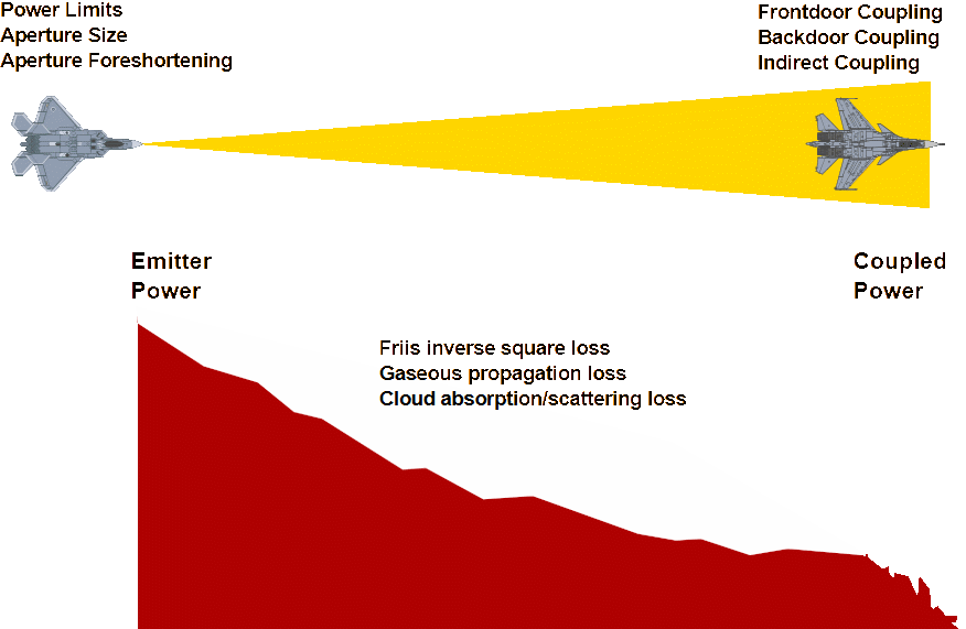
The basic model for all such engagements is that of a transmitting antenna producing a flow of microwave power through a narrow pencil-beam mainlobe, across some distance to the target, where this power couples into the target and produces a damaging or disruptive effect.
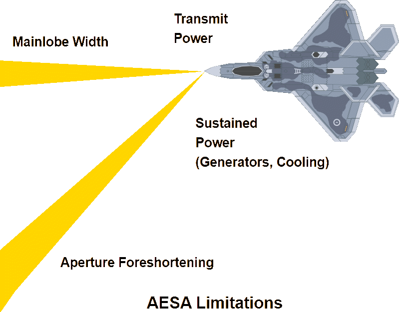
Emitted power is a function of the design of the AESA or ESA design. In terms of the parameters of interest, such radars will emit continuous pulsed power ratings of the order of 2–5 kW continuous, and >10 kW peak, in the X-band, and given antenna aperture sizes, be capable of transmitting with a mainlobe –3 dB (half-power) beamwidth of the order of 2.5–3º, in a fighter radar, refer Figure 1. Mainlobe width will be similar for most designs as it is constrained by airframe geometry. Aperture foreshortening effects will increase mainlobe width with increasing mainlobe off-boresight angle [38,42].
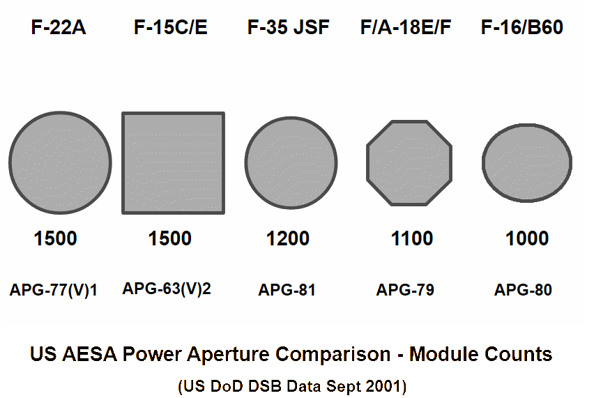
Representative AESA transmit receive model power ratings are of the order of 2 W continuous, and 10 W peak, with incremental development expected to result in progressive growth of power output over time. The principal limitation arises from the capacity of the liquid cooling system to extract waste heat from the AESA, and current density in semiconductor driver transistors [6].
Conventional X-band ESA fighter radars with peak power ratings of 20 kW have been reported, using ganged travelling wave tube transmitters and hybrid ESA antenna arrays. Given similar antenna aperture sizes, cardinal parameters will be similar to AESA radars of equivalent power ratings [4,5].
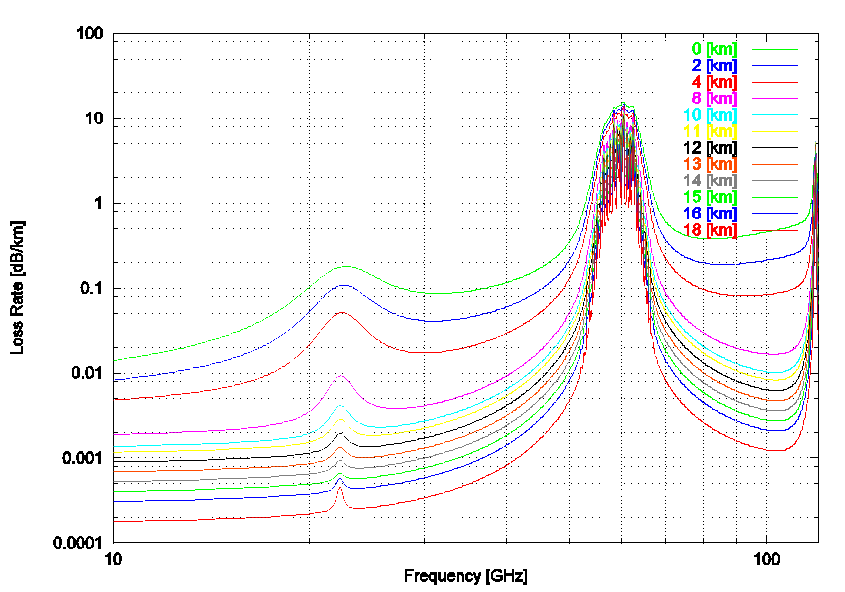
The emitted power must propagate over the distance between the radar and the target, and will experience propagation losses with increasing distance. While inverse square law or Friis loss will be dominant, power transfer efficiency is an issue and other loss components must be considered. In the X-band, gaseous losses due to water vapour and oxygen will increase with decreasing operating altitude, and cloud absorption losses are likely to dominate where cloud must be penetrated [21].
In practical terms, for any AESA or ESA design and target type, useful engagement range will be a function of both altitude and weather conditions in the volume of space between the targets.
The propagation science to assess such losses is mature, and many simulation programs exist which can be employed to produce quite accurate estimates [29].
Power arriving at the target must be coupled into the internal cavities, cabling and, where applicable, waveguides in the target to produce disruptive or lethal effect. Coupling effects into targets can be broadly divided into ‘front-door coupling’ and ‘back-door coupling’ effects [41].
Front-door coupling effects occur when impinging radiation enters via existing antenna apertures on a target.
These may be associated with radar, navigation equipment, communications equipment, or passive radar warning or homing equipment. Where the antenna aperture in question provides a good impedance match at X-band, and its aspect permits a large projected area, high coupling efficiency may be achieved. Under such conditions an effective aperture gain of the order of >0 dB is feasible, and in the instance of an on boresight X-band radar antenna, the full gain of the order of 30 dB may be realised.
Indirect front-door coupling may arise where the geometry of the target permits the coupling and propagation of surface travelling or creeping waves [35]. In such a situation, impinging power, in which an electric field component exists in the plane of incidence, forms a travelling wave which propagates along the skin of the target and couples in via any antenna apertures which are able to couple at that wavelength. This effect can potentially yield a high coupling efficiency due to the large projected area of the target’s skin from many aspects, and will be limited primarily by the design of antenna apertures, which if implemented well, should exhibit low coupling from the surrounding skin. To date there is no open research covering indirect front-door coupling.
Back-door coupling arises when microwave radiation enters via apertures which are not intended for the reception or transmission of microwave radiation. Such apertures typically include cooling grilles, inlet and exhaust ducts, gaps between panels, drain holes, and any other discontinuities which exist in the skin of the target, and which provide a path into internal cavities. From a physics perspective, such apertures (if of a size comparable to or greater than the wavelength of the impinging X-band radiation) will behave as slot radiators, with a gain dependent on the geometry and impedance matching between the exterior and the internal cavity. Such apertures may be approximated as slot radiators in an infinite sheet, where the orientation of the aperture and relative polarisation of the impinging radiation determine the coupling mode [30].
Indirect back-door coupling effects are analogous to indirect front-door coupling effects, and arise where surface travelling waves might couple into an aperture. This may arise where the orientation of the aperture permits a circumferential current to flow through the skin surrounding the aperture [35].
Analytical solution of both front-door and back-door coupling effects can be unusually difficult, due to the complex geometries involved and difficulty in estimating coupling efficiency of most apertures, especially those not intended for X-band signal reception.
Once power has entered the cavity behind an aperture, it can couple and propagate into any electronic hardware which may be located in close proximity, to produce disruptive or damaging effects. Cables, where these have suitably low-loss behaviour, can also propagate power deeper into the target, resulting in further damage or disruption.
Considerable research has been recently performed in modelling the behaviour of cavities containing complex internal structures. This is representative of computer equipment, but also other electronic equipment, in a typical back-door coupling situation. The approach which has yielded best results to date is that of modelling the cavity as a chaotic scattering cavity, where power entering the cavity experiences multiple internal bounces and resonances, which are a function of the internal geometry of objects inside the cavity. To date published work covers both single-port and multiport cavities. The former represent coupling into equipment, the latter into equipment or airframe cavities from whence power can propagate further into the target [15,16,17,18,19,46,47].
From a coupling perspective, there is clearly considerable merit in using circular polarisation at the radar antenna, where the opportunity exists to do so, as this maximises the statistical opportunities for coupling. A further advantage can be realised by chirping the radar waveform over at least one octave, again to maximise coupling opportunities [25].
Damage and disruption effects have been well researched, recently. Disruptive effects arise when the microwave radiation produces unwanted voltages on analogue and digital signal lines, and state changes in digital logic have been observed. Typically, chaotic voltages are superimposed on the signals flowing through circuits, as a result of non-linear interactions between semiconductor components and the microwave signal. Damage effects arise due to dielectric breakdowns and junction breakdowns, where the microwave radiation forces voltages above safe limits for specific semiconductor devices [40].
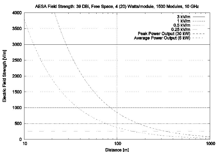
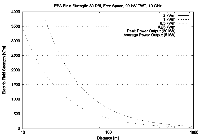
Some empirical work has been performed which identifies lethal field strengths. Commercial electronics are destroyed by exposure to magnitudes between 3–10 kV/m [22].
Figure 6 plots the achievable field strength in V/m versus distance, for representative AESA and ESA configurations. Lethal effect can only be produced at very short distances, but disruptive effect is feasible at distances comparable to those for gun engagements, of the order of 200–300 m for a field strength of 250 V/m, refer Figure 6. Hardware which is susceptible to lower field strengths would extend effective range further.
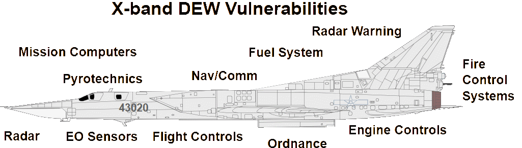
Military targets, such as combat aircraft or missiles in flight, contain also electro-explosive initiators for warheads, and often other pyrotechnics for emergency functions. These can also be vulnerable to microwave radiation. There is a large pool of extant literature and standards dealing with hazards of electromagnetic radiation to ordnance (HERO) and to fuel (HERF), which identifies unsafe power levels [7,23]. Unsafe power levels at X-band are of the order of 60–600 V/m (1–10 mW/cm2) for ordnance, and 50 kV/m (5 W/cm2) for exposed aviation fuel. There is no known research to date on microwave induced ignition in fuel ullage spaces, should these be penetrated, but the power demands suggest this is the domain of HPM devices rather than AESAs or ESAs.
The model in Figure 6 indicates that electro-explosively initiated pyrotechnics are an attractive target for microwave attack by AESA or ESA. Assuming a 600 V/m field strength, effect could be produced at ranges of 100–150 m. If we assume a 60 V/m lethal field strength, ranges extend to the order of 1 km.
In practical terms, should a disruptive field strength be achieved and coupled into onboard electronics, complex airborne targets such are aircraft are apt to experience transient failures in mission computers, stores management computers, embedded computers in subsystems (which may include engines and flight control systems) and various other items of mission avionics, including radar, electronic warfare, and communications equipments. These have the potential to render the target unflyable or non-mission capable. Less complex targets such as cruise missiles and surface to air missiles may experience loss of control, or loss of navigational position. A disruptive field strength thus may be adequate to destroy the target.
Lethal field strengths, capable of inflicting permanent damage on avionics, initiating pyrotechnic devices, or even igniting fuel vapours in ullage spaces, would likely result in the immediate destruction of the target, or rendering it incapable of performing its mission until lengthy repairs are performed.
In summary, a significant number of constraints exist in attempting to inflict disruptive effects or lethal effects using a high power AESA or ESA radar on an airborne, or other, target. For characteristic fighter radar performance, useful effect is produced at ranges comparable to those seen in gun engagements.
Engagement cycles and radar adaptations
Engagement cycles are a characteristic feature of all weapons, and AESA or ESA radars adapted as microwave weapons are no exception.
A typical engagement cycle involves the initial detection of a target, tracking of the target, identification, firing of the weapon, and kill assessment—see Figure 7.
X-band AESA and ESA radars are used primarily as acquisition, tracking, and fire control sensors in air combat. In this regime, these devices may be cued to a target by an external information source, such as a ground-based search radar, or an airborne early warning radar, or they may acquire the target by using one of several search modes, examples including velocity-search, range-while-search, or track-while-scan [31].
These radar modes are typically optimized for long- or medium-range missile engagements, and will typically be designed to gather target position and velocity information with accuracy commensurate with that required to support the kinematics of a missile shot.
Once the target is within the kinematic envelope of the missile, one or more missiles may be fired, and these will be provided with mid-course datalink updates, transmitted by the radar, until the missiles’ guidance seekers can acquire the target and initiate terminal homing.
If the initial engagement has failed, and the aircraft closes with the target, short range radar modes will be invoked to permit engagement with short range missiles, typically infrared or optically guided, or an onboard gun. Radar modes for such close in engagements are yet again optimized around the gathering of kinematic data, to permit calculation of engagement envelopes for weapon shots. In particular, range and closure rates are critical given the limited kinematic envelope of short-range missiles and guns. Given the potentially high closure rates, update rates for position measurements may be high.
In an electronic countermeasures environment, it is likely that the opposing aircraft will actively jam the radar to deny accurate range and velocity information. The effectiveness of such short-range jamming will depend on the X-band radar cross section (RCS) of the target, jammer-emitted power, and the power-aperture performance of the radar being jammed. In many instances, burn-through will occur [36,43].
In short-range engagements it is not uncommon for the radar to employ monopulse angle tracking techniques, due to their high resistance to amplitude based jamming techniques, and difficulty in implementing wavefront angle jamming techniques. A typical mode would be a dual-plane monopulse angle track mode, with a high PRF to permit a high update rate [38,42].
This characteristic engagement cycle for kinematic weapons is not ideal for a microwave weapon, and will require some adaptation.
The effective range at which a microwave weapon can achieve a lethal or disruptive effect upon the electronics of a target will depend on emitted power levels, distance between the target and emitting radar, propagation losses, target coupling characteristics, and the electromagnetic hardness of the target electronics, ordnance, and fuel systems. The range at which a viable effect on the target may be produced could easily vary by orders of magnitude, and not be known a priori.
Calculating or otherwise modelling the complete power transfer relationship between the emitting AESA and the vulnerable components of a target will present genuine difficulties, due to the complexity of the propagation and especially coupling and damage-effect mechanisms. Variations in build quality between targets may also impact lethal or disruptive ranges. It is therefore expected that empirical measurement will be required to establish both ranges, for specific target types. From an order-of-magnitude perspective, the range can be estimated as comparable to gun engagement ranges. From an operational perspective this presents some interesting constraints. It is clear that additional radar modes will be required to support engagements using the AESA or ESA as a microwave weapon.
As the AESA and ESA can effect engagements at the speed of light, kinematics of the target are only of interest in terms of range to the target being within an expected or estimated lethal or disruptive level. The target must however be tracked, and dwell time for the engagement budgeted for.
This indicates that a specific mode for ‘microwave attack’ will be required, which will combine a single target track precision tracking regime, interleaved with maximum power emission bursts to effect disruption or damage, the latter keyed by pilot or operator trigger. In operation, this mode would initiate a fine track, preferably using a dual-plane monopulse mode, and continuously measure range to the target, and propagation losses between the AESA or ESA and target. The latter can be estimated by measuring amplitude of the return and comparing it against known RCS performance for the target and its aspect.
Once disruptive range is achieved, an audible or visual cue similar to existing schemes for short-range missiles would be activated to alert the pilot or operator. The cue would then change, as the range to target decreases and lethal range is approached. The pilot or operator would then initiate firing with a trigger, upon which the AESA or ESA would cycle between illuminating the target at maximum power levels, and continuing its tracking. The illumination mode would be chirped, and if the radar has capability for circular polarization, it would be used.
Further observations apply. The first is that uncertainties in target vulnerability dictate that microwave attack should not be attempted by an aircraft which lacks the capability to defeat the opponent in a short-range engagement as, should the microwave attack fail, the target could engage and destroy the attacker.
The other is that the potential of fighter AESAs or ESAs to be operated for very short periods at peak power ratings exceeding acceptable limits for conventional radar modes should be explored. If the current density limits of the radars modules, or TWT power ratings, permit higher peak powers for very short durations, these would increase the useful disruptive and lethal ranges.
Kill assessment will present no difficulty, where the target experiences loss of control, or ignition of fuel or ordnance is achieved. Disruptive or avionic damage to mission systems may be more difficult to determine, and may only be discernable by the kinematic behaviour of the target, such as a major change in direction, or cessation of radio-frequency emissions.
Conclusion
This paper has explored a range of issues arising in the application of AESA and ESA X-band radars as DEW.
The application of circular polarisation at the radar antenna, a technique shown to be useful for HPM weapons, will maximise statistical opportunities for coupling power into targets. Chirping the radar waveform over at least one octave also maximises coupling opportunities.
It will be necessary to design radar modes specifically for the purpose of microwave attack, to provide the capability to interleave operator-controlled high-power emissions with necessary tracking waveforms.
Order-of-magnitude estimates of achievable effect using a representative radar configuration indicate that a microwave attack regime will produce useful effect only at ranges comparable to those found in gun engagements.
Future research remains to be performed in exploring indirect coupling mechanisms, where the skin of the target contributes to the capture and coupling of incident power.
References
M. Abrams, “The Dawn of the E-Bomb”, IEEE Spectrum Online, 2003, URL: http://www.spectrum.ieee.org/ WEBONLY/publicfeature/nov03/1103ebom.html, accessed September 2006.
J. Baird, et al, “Longitudinal Shock Wave Depolarization of Pb(Zr52Ti48)O3 Polycrystalline Ferroelectrics and Their Utilization in Explosive Pulsed Power”, Proceedings of the 14th APS Topical Conference on Shock Compression of Condensed Matter, 31 July–5 August 2005.
A. Butler, “Risky Business”, Aviation Week & Space Technology, Vol. 163, pp. 42–43, 25 September 2006.
Beliy Yu.I., Zagorodniy V.G., “"Ирбис" готовиться к прыжку (The Irbis prepares to leap)”, Авиасалоны мира (World Aviation Salon), No. 5, 2006, pp. 22–25, URL: http:// www.niip.ru/main.php?page=library_sky18, accessed April, 2007.
Yu. I. Beliy and V.G. Zagorodniy, “РЛСУ "Ирбис-Э"—радар нового поколения (The Irbis-E—a new generation radar)”, Аэрокосмическое обозрение (Aerospace Review), No. 1, 2006, pp. 20–22, URL: http://www.niip.ru/ main.php?page=library_sky17, accessed April, 2007.
Defense Science Board, Report of the Defense Science Board Task Force on Future DoD Airborne High-Frequency Radar Needs/Resources, Office of the Under Secretary of Defense For Acquisition and Technology, Washington DC, 2001 URL: http://handle.dtic.mil/100.2/ADA391893, accessed September, 2006.
Electromagnetic Radiation Hazards, US Navy website, https://ewhdbks.mugu.navy.mil/RADHAZ.HTM, accessed September 2006.
D.A. Fulghum and D. Barrie, “Thug Zapper”, Aviation Week and Space Technology, Vol. 161, No. 4, p. 34, July 2004.
D.A. Fulghum, “New Energy Direction”, Aviation Week and Space Technology, Vol. 161, No. 18, pp. 24–25, November 2004.
D.A. Fulghum and D. Barrie, “Directed-Energy Weapon for UAV, Cruise and Air-To-Ground Missile Payloads Nears Production,” Aviation Week & Space Technology, Vol. 161, p. 34, 26 July 2004.
D.A. Fulghum, “E-10 Radar Secretly Designed To Jam Missiles”, Aviation Week & Space Technology, Vol. 162, p. 24. 30 May 2005. URL: http://esc.hanscom.af.mil/ESC-PA/ The%20Integrator/2005/July/07072005/07072005-14.htm, accessed September 2006.
D.A. Fulghum, “Zap It’s Here”, Aviation Week and Space Technology, Vol. 163, No. 9, p. 52, September 2005.
D.A. Fulghum, “Northrop Grumman, L-3 Turn F/A-22 Radar Into Wide-Bandwidth Data Link”, Aviation Week & Space Technology, Vol. 163, 11 December 2005, URL: http://www.aviationnow.com/avnow/news/channel_awst_story.jsp?id=news/12125p2.xml, accessed September 2006.
D.A. Fulghum, “Microwave Weapons Emerge”, Aviation Week & Space Technology, Vol. 162, 13 June 2005, URL: http://www.reprintbuyer.com/nxtprint/aviationweek_raytheon.pdf, accessed September 2006.
V.L. Granatstein, “Effects of High Power Microwaves and Chaos in 21st Century Analog and Digital Electronics”, MURI 01 Final Review, Multidisciplinary University Research Initiative, 14 July 2006, Albuquerque, NM, URL: http://www.ireap.umd.edu/MURI-2001/, accessed September 2006.
S. Hemmady et al, “Universal Statistics of the Scattering Coefficient of Chaotic Microwave Cavities”, Physics Review E, 71, 056215, 2005. URL: http://www.csr.umd.edu/ anlage/RCM/index.htm, accessed September 2006.
S. Hemmady et al, “Universal Impedance Fluctuations in Wave Chaotic Systems”, Physics Review Letters, 014102, 2005. URL: http://www.csr.umd.edu/anlage/RCM/index.htm, accessed September 2006.
S. Hemmady, et al, “Universal Properties of 2-Port Scattering, Impedance and Admittance Matrices of Wave Chaotic Systems”, Physics Review E, URL: http://www.csr.umd.edu/ anlage/RCM/index.htm, accessed September 2006.
S. Hemmady, et al, “Aspects of the Scattering and Impedance Properties of Chaotic Microwave Cavities”, Acta Physica Polonica A, 109, 65, 2006. URL: http://www.csr.umd.edu/ anlage/RCM/index.htm, accessed September 2006.
S. Hemmady, et al, "Experimental Test of Universal Conductance Fluctuations by means of Wave-Chaotic Microwave Cavities”, submitted to Phys. Rev. B URL: http://www.csr.umd.edu/anlage/RCM/index.htm, accessed September 2006.
L.J. Ippolito, Propagation Effects Handbook for Satellite Systems Design—A Summary of Propagation Impairments on 10–100 GHz Satellite Links With Techniques for System Design, Fourth Edition, NASA Reference Publication 1082(04), Westinghouse Electric Corporation, Baltimore, Maryland, USA, 1989.
M. Jung and Th.H.G.G. Weise, “High Power Microwave Technologies For Vehicle Integration”, 14th IEEE International Pulsed Power Conference 2003, Digest of Technical Papers, PPC-2003, Vol. 1, pp. 474–476, 2003.
M. Koch, W. Zappe, M. Camp, “The Safety Of Ordnance in High Frequency Electromagnetic Fields”, Proceedings of the 2003 IEEE International Symposium on Electromagnetic Compatibility, EMC 03, Vol. 1, pp 489–492, 11-16 May 2003. URL: http://www.geml.uni-hannover.de/grund_elektr/ publikationen/publikation21.pdf , accessed September 2006.
C. Kopp, “The Electromagnetic Bomb - A Weapon of Electrical Mass Destruction”, Air Chronicles Paper, USAF CADRE Air Chronicles, October 1996, URL: http://www.airpower.maxwell.af.mil/airchronicles/kopp/apjemp.html, accessed September 2006.
C. Kopp, An Introduction to the Technical and Operational Aspects of the Electromagnetic Bomb, Air Power Studies Centre Paper No. 50, Royal Australian Air Force, November, 1996.
C. Kopp, A Doctrine for the Use of Electromagnetic Pulse Bombs, Air Power Studies Centre Paper No. 15, Royal Australian Air Force, July 1993.
Kopp C, “Information Warfare and Info-terrorism—Part 2”, Asia/Pacific Open Systems Review, Computer Magazine Group, Sydney Australia, pp. 47–52, 1997, URL: http:// www.ausairpower.net/OSR-0297.html, accessed September 2006.
C. Kopp and R.D. Pose, “Electromagnetic Considerations For Computer System Design”, Computer Architecture '97 Selected Papers of the 2nd Australasian Conference, Springer-Verlag Singapore Pte Ltd, Singapore, pp. 269–287, 1997.
C. Kopp and C.S. Wallace, TROPPO—A Tropospheric Propagation Simulator, School of Computer Science and Software Engineering, Monash University, Melbourne, Technical Report 2004/161, 2004.
J.D. Kraus Antennas, 2nd edition, McGraw-Hill Companies, New York, p. 624, 1988.
D. Lynch, and C. Kopp, “Multifunctional Radar Systems for Fighter Aircraft”, Chapter 5, in M. Skolnik, Radar Handbook, Third Edition by McGraw-Hill, Draft Chapter.
T. McKenna, “Flash in the Pan”, Journal of Electronic Defense, Vol. 26, No. 5, pp. 46–52, May 2003.
Raytheon, Vigilant Eagle—A Revolution In Airport Protection, URL: http://www.raytheon.com/feature/vig_eagle0706/, accessed September 2006.
D.L. Rockwell, “Fighters Feature Electronic Attack”, Aerospace America, American Institute of Aeronautics and Astronautics, February 2006, URL: http://www.aiaa.org/ aerospace/images/articleimages/pdf/AA_Feb06_EOE.pdf, accessed September 2006.
J.F. Shaeffer, M.T. Tuley, and E.F. Knott, Radar Cross Section, Second Edition, Artech House, Norwood, Ma, 1993.
R.J. Schlesinger, Principles of Electronic Warfare, Peninsula Publishing, Los Altos, Ca, 1979.
S.I. Shkuratov, et al, “Transverse Explosive Shock-Wave Compression of Nd2Fe14B High-Energy Hard Ferromagnets: Induced Magnetic Phase Transition”, Proceedings of the 14th APS Topical Conference on Shock Compression of Condensed Matter, 31 July–5 August 2005.
M.I. Skolnik, Radar Handbook, Second Edition, McGraw-Hill Professional, 1990.
V. Slyusar,“Generatory Supermoshchnykh Elektromagnetnykh Impul’sov v Informatsionnykh Voynakh (High Power Electromagnetic Pulse Generators in Information Warfare)”, Elektronika: Nauka, Tekhnologia, Biznes, May 2002.
F. Sonnemann and J. Bohl, “Susceptibility and Vulnerability of Semiconductor Components and Circuits against HPM”, Proceedings of XXVIIth URSI General Assembly, Maastricht, Union Radio-Scientifique Internationale, 2002. URL: http:// www.ursi.org/Proceedings/ProcGA02/papers/p1352.pdf, accessed September, 2006.
G.W. Staines, High Power Microwave Technology - Part IV, Military Applications of High Power Microwaves, Salisbury, DSTO ERL, Electronic Warfare Division, Department of Defence, Australia, draft paper, 1993.
G. Stimson, Introduction to Airborne Radar, 2nd edition, SciTech Publishing, New Jersey, 1998.
L.B. Van Brunt, Applied ECM, Electronic Warfare Engineering, Inc., Dunn Loring, Va, 1978.
C. Wilson, High Altitude Electromagnetic Pulse (HEMP) and High Power Microwave (HPM) Devices: Threat Assessments, CRS Report for Congress, RL32544, Congressional Research Service, The Library of Congress. 2006.
X. Zheng, et al, “Statistics of Impedance and Scattering Matrices in Chaotic Microwave Cavities: Single Channel Case”, Electromagnetics, Vol. 26, No. 3, 2006. URL: http:// www.csr.umd.edu/anlage/RCM/index.htm, accessed September, 2006.
X. Zheng, et al, “Statistics of Impedance and Scattering Matrices of Chaotic Microwave Cavities with Multiple Ports”, Electromagnetics, Vol. 26, No. 37, 2006. URL: http:// www.csr.umd.edu/anlage/RCM/index.htm, accessed September, 2006.
X. Zheng, et al, “Characterization of Fluctuations of Impedance and Scattering Matrices in Wave Chaotic Scattering”, Physics Review E, 73, 046208, 2006. URL: http:// www.csr.umd.edu/anlage/RCM/index.htm, accessed September, 2006.