
Volume 10, Number 3, November 2007
Simulation Model For Submunition Warheads
- 1 Military Equipment and Technologies Research Agency, PO Box 51-16, 053070, Bucharest, Romania.
- 2 University POLITEHNICA of Bucharest, Splaiul Independentei 313, Postal code 060032, Romania.
Abstract
One method of enhancing the target effect of modern artillery and rocket systems is to use submunition warheads. This paper proposes an analysis model for the performance of submunition warheads. In developing this model we have taken into account two design aspects characteristic of this type of munition: a uniform distribution for submunition impact points, and a surface density for these, within imposed limits. In this paper we analyse three essential aspects of design and submunition warhead (cluster warhead): choosing the right model for simulation of the submunition trajectory within the constraints of minimum time and numerical precision; choosing the method of ejecting the submunition, imposing the condition of optimal dispersion; and choosing the altitude for the submunition ejection, also in the condition of optimal dispersion.
Calculation of average submunition trajectories with point mass model
Submunitions ejected from clustered warheads follow individual trajectories after the burst moment, each of which is influenced by the initial conditions at the burst point on the rocket trajectory (velocity, ejection angle, and drag coefficient) and by the atmospheric conditions (such as wind, temperature, and humidity). In this paper we model a theoretical dispersion of submunitions on the basis of a theoretical model for the trajectory without perturbation of an ideal submunition, which has the average characteristics of the submunition real trajectory cluster. This means for example, that the mass of the hypothetical submunition is equal to the mean mass of all submunitions in the pack, and similarly for the drag coefficient and for the burst launch angle. The movement and the position of this hypothetical submunition can be given by [5]. This model type is also exemplified in [1–4], which show similar applications using algorithms based on random initial conditions:
with the link between velocities:
where:
m: Mass of the submunition;
: Absolute velocity—the velocity of the hypothetical submunition with respect to ground-fixed axes (inertial frame);
: Aerodynamically velocity—the velocity of the hypothetical submunition with respect to air;
: Wind velocity—the velocity of the air with respect to ground-fixed axes;
: Acceleration due to gravity; and
: Drag force,
where: ρ is density of air; v is aerodynamic velocity magnitude, S is reference cross section area and CD is drag coefficient.
If we suppose that during the free fall we can split the trajectory into piecewise elements of constant velocity, we can define the coefficient:
Combining (1), (2), and (3):
Note that (4) it is an affine equation with constant coefficient in generic form:
with the well-known solution:
Using this result we can write directly the solution of (4), which is valid for the piecewise elements of the trajectory with constant velocity [5]:
Integrating again versus time we can obtain the current position of the submunition with respect to ground-fixed axes [5].
Taking in consideration the acceleration of gravity and the wind velocity projection versus the inertial frame:
and allow ,so that (7) and (8) become respectively:
and:
Finally, we make a comparison between the result obtained from the closed-form solution model (10) and (11) and the numerical integration of the point-mass model in (1).
For a hypothetical case, without wind, we considered the following deterministic initial conditions: velocity m/s; altitude m, climb angle and track angle .
The more general case is a combination of deterministic , and the random initial conditions :
where the random initial condition are considered to have normal distribution.
The link between the initial conditions for and from equations (10) and (11), are given by:
By numerical integration of equations (1) and solving the analytical relations (10) and (11), for deterministic initial conditions we obtained the velocity diagram represented in Figure 1 and the projection of the trajectory in the vertical plane represented in Figure 2.
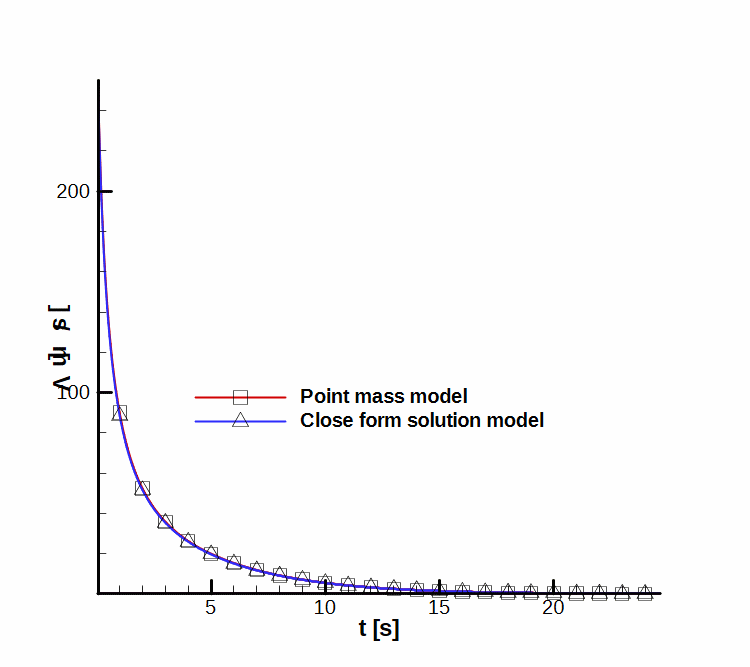
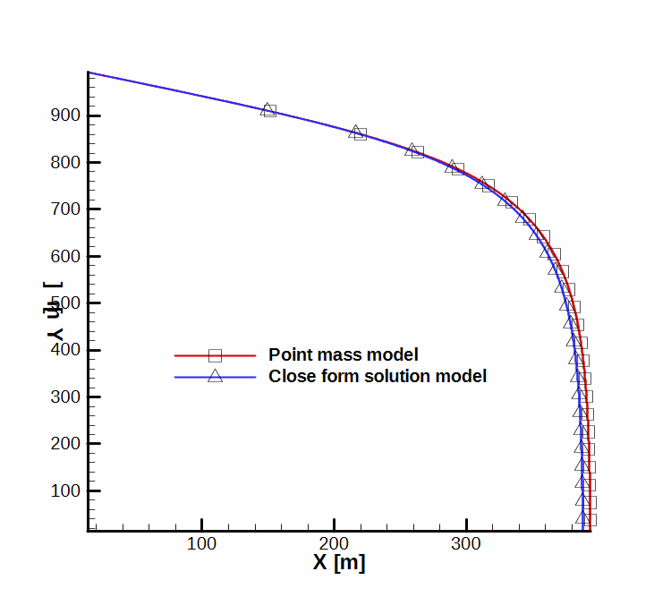
Analytical results were obtained by splitting the time interval in 1,000 parts. For the numeric calculus, we used the predictor corrector algorithm, and controlled the relative error which was while the absolute error was .
Conclusion: Contrary to what we expected, for an adequate number of intervals, the calculation time for the numerical solution is shorter than the calculation time for the analytical solution. Therefore, we recommend the use of the numerical integration algorithm for time-critical applications such as those used in ballistic software to solve the “reverse ballistic problem” in the fire control system.
Options for the submunition placement in the warhead and for their ejection
As mentioned in [6], to ensure a uniform distribution of submunition impact points, we have to analyze and try to optimize the warhead set-up and functioning. We considered two types of placement and ejection of the submunition:
- A frontal placement and an ejection in sequence from one of the warhead ends (see Figure 3); and
- a radial placement and a simultaneous ejection, as a result of lateral detachment of the warhead (see Figure 4).
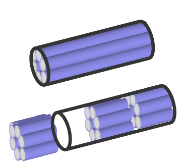
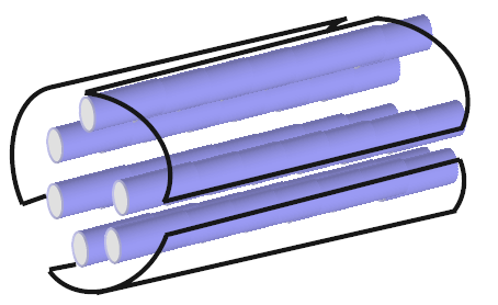
To perform this analysis, a kinematic model was built, which integrates recurrently the movement equations of each submunition, the dispersion of the impact points being affected by the initial conditions in each case.
Two types of initial conditions were used:
- deterministic initial conditions for velocity, height, and average values of launching angles (climb angle, track angle):
- random initial conditions for dispersion of the burst launching angles.
(15)
Because our study was focused on warheads of aerodynamic stabilized rockets, we neglected the effect of initial roll rate.
The model was used to obtain a set of results by analyzing the distribution of impact points with respect to the submunition placement in the warhead.
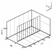
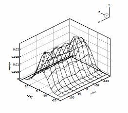
Figures 5 to 9 are plotted showing the distribution of submunitions in three dimensions: x, y, and z (as shown in the figures). The parameter chosen for the distribution was the number of submunitions, n, at a particular impact point, divided by the total number of submunition per surface element, ntot. This parameter n/ntot is similar to the distribution function used in random function theory: by integrating it on a certain surface we obtain the probability that all the submunitions hit the target. Obviously if the target surface contains the distribution surface, the probability is one; otherwise if it intersects or is included in the distribution surface, the probability is less than one.
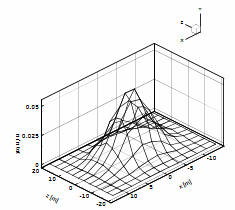
In Figure 5 a hypothetical case is presented: all the submunitions are ejected simultaneously, directionless; the initial conditions that generate the dispersion are those induced by the launching angles dispersion. Figures 6 and 7 show the distribution for warhead with sequential, longitudinal ejection, within 1 s, along a trajectory with speed and trajectory angle invariant In Figure 6 the initial conditions are not random; in Figure 7 they are. There is a noticeable oblong distribution in all situations, particularly for sequential ejection.
Figures 8 and 9 present the case of the warhead with radial, simultaneous ejection—without random initial conditions in Figure 8 and with random initial conditions in Figure 9. This kind of placement ensures a more uniform distribution, which is almost equal in all directions.
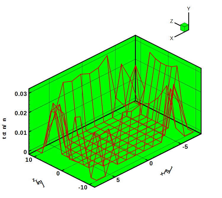
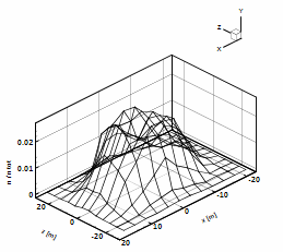
Conclusion: The comparative analysis of these two types of submunition placements shows that simultaneous radial ejection is preferable, because it ensures a more uniform distribution of the submunition impact points.
Determination the optimal height of burst for submunition ejection
The initial conditions for submunition ejection are not independent parameters. That is, for a certain trajectory of the rocket, the rocket trajectory angle and velocity depends on the height. Consequently, the only parameter that can be optimized is the height of burst.
Theoretically it is possible to enforce values for velocity or for the rocket trajectory angle instead of height but this is not suitable in practice. So, we shall add to the qualitative images of the shape of dispersion surface, a summary of a quantitative analysis on the parameters of the dispersion.
When investigating various calculus models results linked to the height of burst, the following bounds on burst height must be taken into account:
- the upper value of burst height is restricted by lower trajectories, where the apex must be greater than the height of burst—this affects the minimum range firings with extended trajectories; and
- the lower value of the burst height is restricted by the working dispersion of time fuse and by the correctness input of firing corrections.
Using the model described earlier, several parametrical dispersion diagrams have been represented with respect to the height of burst. For this group of applications we integrated (1) considering various burst heights for a warhead with simultaneous radial ejection with a climb and track angle at the height of burst , and a velocity m/s.
Figure 10 presents the probable error in range (along x axis) , Apb, and in deflection (along z axis), Abd versus height of burst. We’ve found out that both errors increase up to 1 km after which they are almost constant.
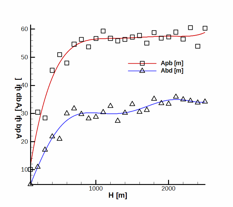
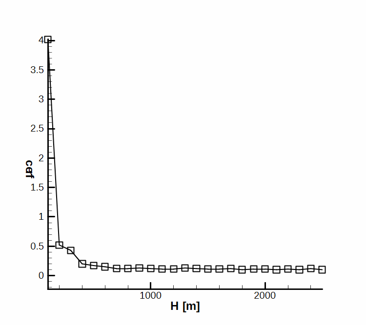
Figure 11 shows the coverage of the dispersion surface. This parameter represents the ratio between the effective surface of one submunition multiplied by the number of submunitions and the total dispersing surface of all of the submunitions. Again, for heights above 1 km, this parameter is almost constant.
In Figures 12 and 13 the CEP (circular error probability) unit radius and the radius of total error circle are presented as a function of burst height. It is noted again, that for heights greater than 1 km, this parameter is almost constant.
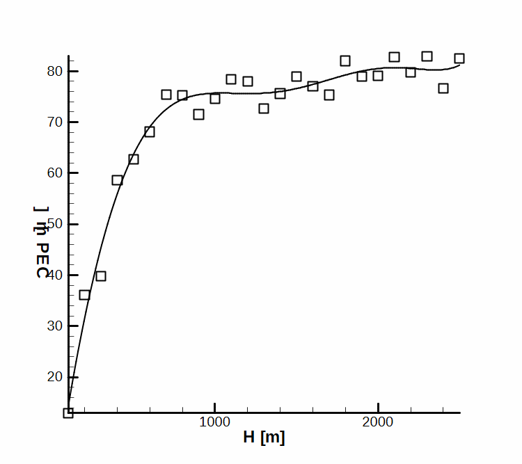
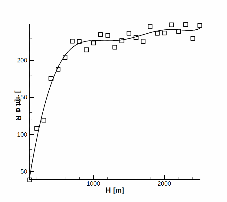
Analyzing these diagrams we note that the submunition group disperses in an optimal way at a height of about 1 km. After ejection, the disturbed initial conditions tend to be damped, and the submunitions follow parallel trajectories toward the horizontal plane of the target. A greater ejection height induces a higher dispersion of lower trajectories in the way that unexpected displacements of the submunitions due to the ground wind influence may occur, a phenomenon that troubles firing accuracy.
Conclusion
In this paper we analysed three essential aspects of design and submunition warhead (cluster warhead):
- choosing the right model for simulation of the submunition trajectory within the constraints of minimum time and numerical precision;
- choosing the method of ejecting the submunition, imposing the condition of optimal dispersion; and
- choosing the altitude for the submunition ejection, also in the condition of optimal dispersion.
For solving these submunition dispersion problems we used numerical integration of (1) with initial random condition (15). This model type is also exemplified in [1–5], which are similar applications using the algorithm based on random initial conditions. It should be noted, however, that the results and the conclusion of this analysis are not general, and are specific to this study case. Therefore we do not recommend making use of this preliminary result in other cases without specific verification.
References
[1] T.V. Chelaru, C.Barbu, and A. Dumitriu, “Calculus Model Used to Build Firing Tables With Low Ammunition Consuming and the Ballistic Module of the Firing Control System for the Fin Stabilized Rockets”, The 31st Internationally Attended Scientific Conference of the Military Technical Academy, Bucharest, 3–4 November 2005.
[2] T.V. Chelaru, „Dinamica zborului—racheta nedirijată”, Ed Printech, martie 2006.
[3] E.S. Ventzeli, Teoria veroiatnostei (“Probability Theory”, in Russian), Ed. Nauka, Moskva, 1964.
[4] R.L. Carmichael, PDAS V5—Public Domain Aeronautical Software, Standard Atmosphere.
[5] STANAG 4355—The Modified Point Mass and Five Degrees of Freedom Trajectory Models.
[6] M. Cernat, “Concepts of Systems Engineering Applied to Unguided Rockets Design”, Journal of Military Technical Academy, Bucharest, May 2005.